


Performance Tests
Performance Verification
4Ć8
Related Information
Read Preparation and Conventions on page 4Ć1. Also, if you are not familiar
with operating the AWG2005, read the subsection, Instructions for OperaĆ
tion, in section 2 before doing any of these procedures.
Equipment Required
The following equipment is required to check the performance of the
AWG2005.
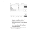
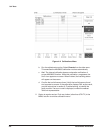
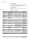
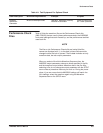
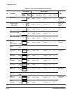
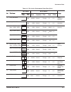
TableĂ4Ć1:ăTest Equipment
Item Description
Minimum Requirements Example Purpose
Precision
termination
Impedance: 50ĂΩ, 0.1%
Connectors: BNC
Tektronix Part 011Ć0129ĆXX Signal termination.
Adapter Connectors: BNC femaleĆtoĆ
dual banana
Tektronix Part 103Ć0090ĆXX Signal
interconnection.
BNC dual input
(TEE) adapter
Connectors: BNC Tektronix Part 103Ć0030ĆXX Signal
interconnection.
BNC cable
(4 required)
Impedance 50ĂΩ
Connectors: BNC
Length: 43 inches
Tektronix Part 012Ć0057ĆXX Signal
interconnection.
Digital Data Out
Cable (Option 04)
Must use example equipment Tektronix Part 174Ć3192ĆXX Used to check
digital data output .
2 X13 header
(Option 04)
Must use example equipment Tektronix Part 131Ć3847ĆXX Used to check
digital data output.
Probe, 10X
(Option 04)
10X probe Tektronix Part P6139A Used to check
digital data output.
Test
oscilloscope
Bandwidth: >250ĂMHz Tektronix TDS500 Series DigitizĆ
ing Oscilloscope or 2400 Series
Digitizing Oscilloscope
Checks output
signals. Used in
many procedures.
Frequency
counter
Frequency range:
10ĂHz to 250ĂMHz
Tektronix DC 5010 ProgramĆ
mable Universal Counter/Timer
*
Used to check clock
frequency.
Digital
multimeter
DC volts range:
0.05ĂV to 10ĂV
Accuracy: ±0.1%
Fluke 8842A Used throughout the
checks to measure
voltage.
Function
generator
Output voltage:
-5ĂV to 5ĂV
Tektronix FG 5010 ProgramĆ
mable Function Generator
*
Used to input the
trigger signal.
Performance Check
disk
Must use example listed Tektronix Part 063Ć1706ĆXX Used throughout the
checks to provide
waveform files.
*
Requires a TM 5000 Series Power Module Mainframe