


Troubleshooting
AWG2005 Service Manual
6Ć65
Do the
horizontal and
/or vertical sync
lock ok?
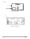
Power the AWG2005 off and
disconnect the cable from J901 on
the monitor module(see Figure 6Ć33)
then power back on.
Do pins 4
and 6 of J901 have
signals similar to
Figure 6Ć34?
Replace the
monitor
module
(page 6Ć42).
Power the AWG2005 off and
disconnect the cable from J901 on
the monitor module(see Figure 6Ć33)
then power back on.
Is pin1 of
the cable at
+15V?
Does
pin 9 of the cable
have a video signal with
the same levels as
in Figure
6Ć35?
Replace the
monitor
module
(page 6Ć42).
Do pins
4 and 6 of the cable
have signals similar
to Figure
6Ć34?
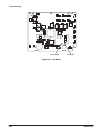
Do pins 2
and 4 of J50 on
the A6 CPU board (see
Figure 6Ć26) have signals
similar to Figure
6Ć34?
Replace the cable.
Are the
cables securely
installed in their sockets
and are the cables
ok?
Securely install
and/or replace
the cables.
Perform the power
supply module
troubleshooting
procedure 1
(page 6Ć61).
Does
J50 pin 7 on
the A6 CPU board (see
Figure 6Ć26) have a video
signal with the
same levels as
in Figure
6Ć35?
Replace the A6
CPU board
(page 6Ć45).
Replace the A6
CPU (page 6Ć45)
or A5 Backplane board
(page 6Ć49).
Is the
problem
fixed?
Yes Yes
Yes
Yes
Yes
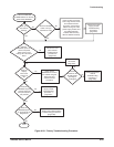
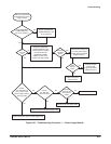
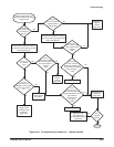
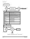
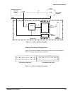
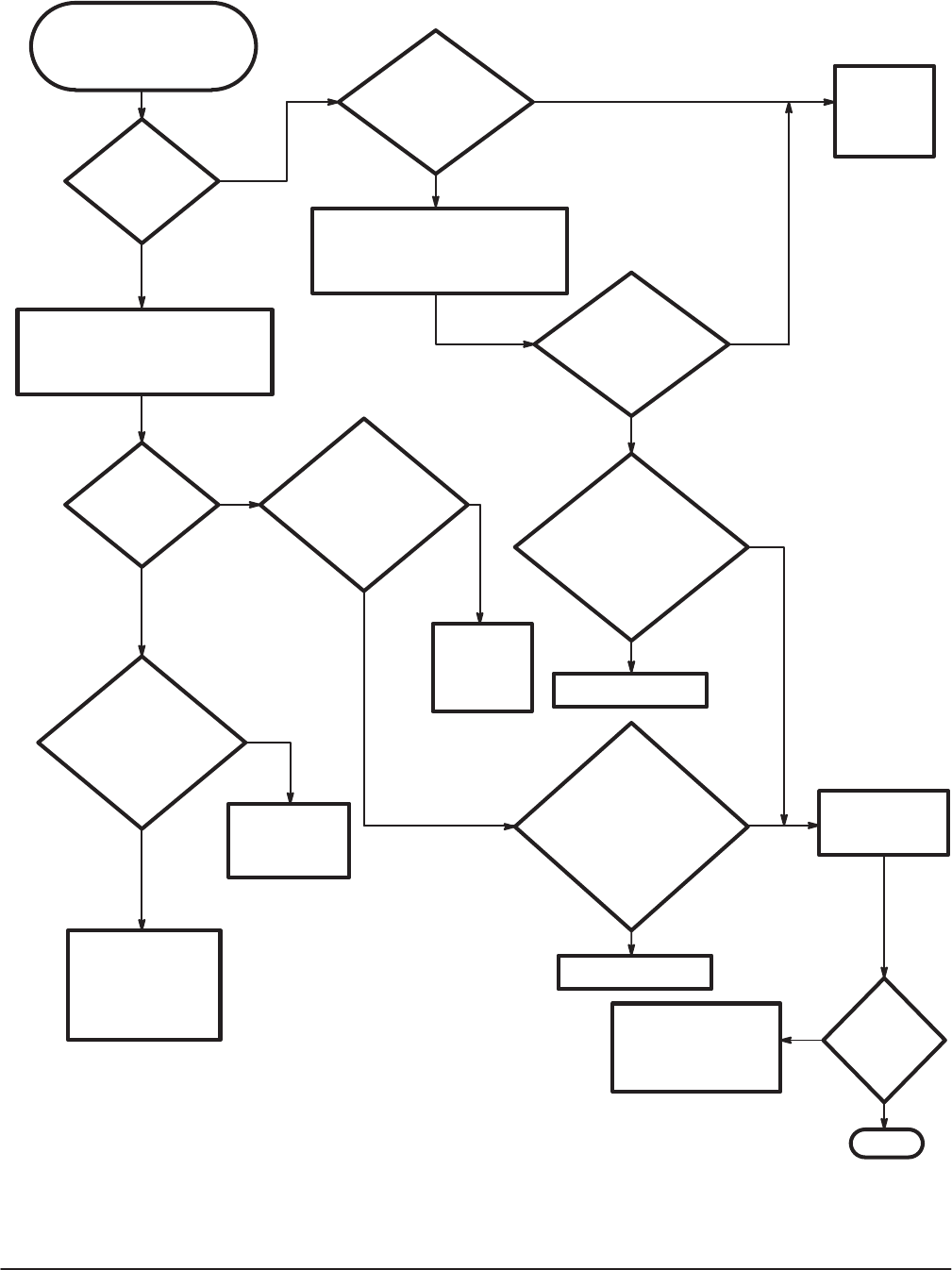
This procedure helps you
determine whether the monitor
module is bad.
Done
No
No
No
No
No
Yes
Yes
No
Yes
No
No
Yes
Replace the cable.
No
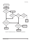
Figure 6Ć32:ăTroubleshooting Procedure 3 Ċ Monitor Module