


Performance Tests
Performance Verification
4Ć34
7. End procedure: Disconnect the DMM.
This procedure checks the pulse response characteristics of the AWG2005
output waveforms at amplitudes of 0.5 and 1ĂV.
Electrical Characteristic Checked: Main Output, Pulse Response, on
pageĂ1Ć12.
Equipment Required: A 50ĂΩ coaxial cable and an oscilloscope.
Prerequisites: The AWG2005 meets the prerequisites listed on page 4Ć7.
Procedure:
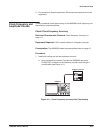
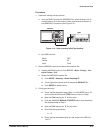
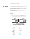
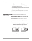
1. Install test hookup and set test equipment controls:
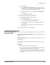
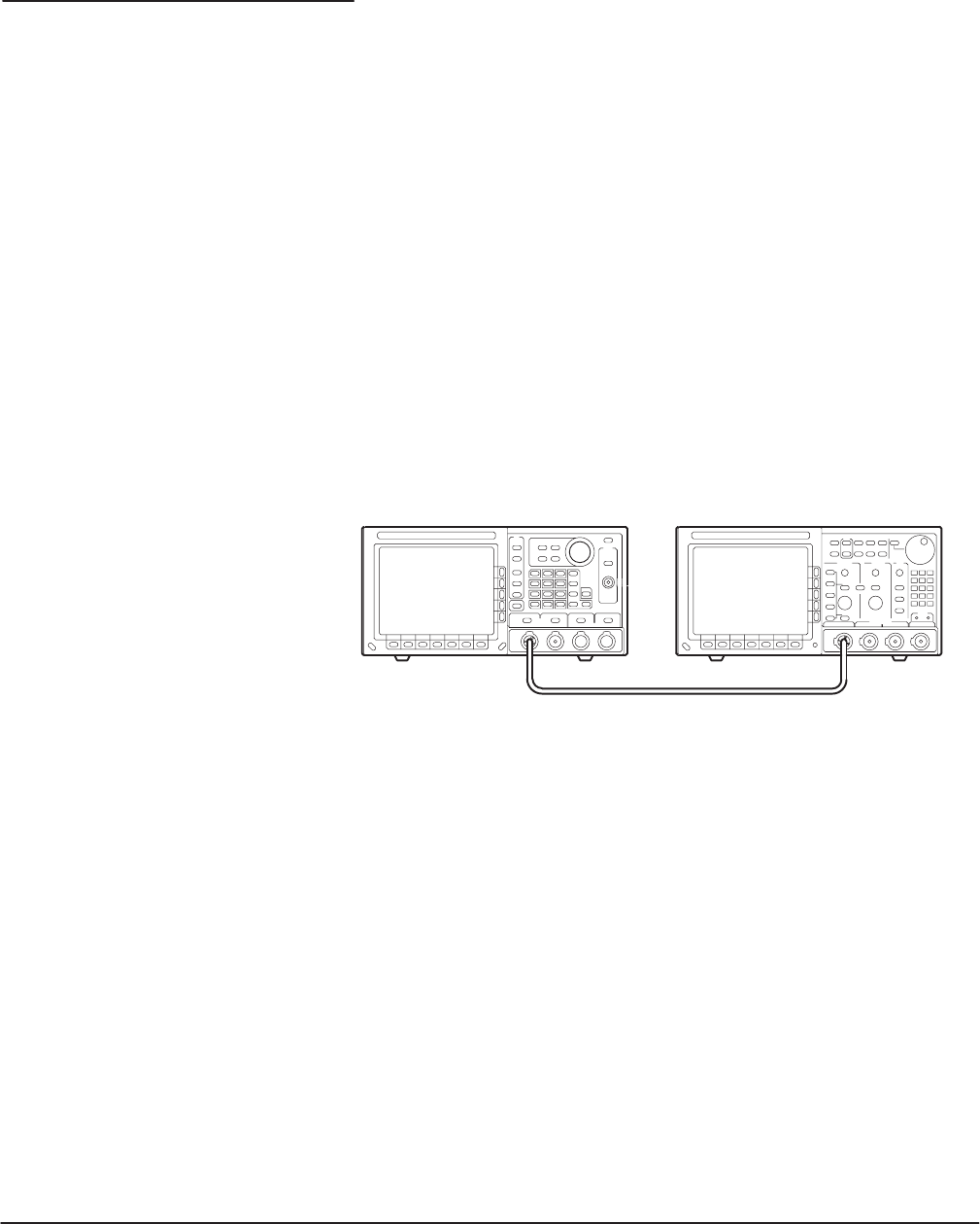
a. Hook up the oscilloscope: Connect the AWG2005 CH1 output
connector through the coaxial cable to the CH1 vertical input conĆ
nector on the oscilloscope (see Figure 4Ć15).
OscilloscopeAWG2005
AWG2005
Figure 4Ć15:ăPulse Response Initial Test Hookup
b. Set oscilloscope controls:
Vertical CH1
Coupling DC
Scale 0.1ĂV/div.
Input impedance 50ĂΩ
Horizontal
Sweep 20Ăns/div.
Trigger
Source CH1
Coupling DC
Slope Positive
Level 0ĂV
Mode Auto
Pulse Response
Check