


Removal and Installation Procedures
AWG2005 Service Manual
6Ć47
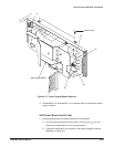
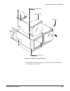
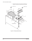
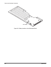
6. Remove A2 AWG board and A11 D/A board: This circuit board is installed
in fourth slot from the top.
a. Disconnect the interconnect cables at J100 and J200 on the A23
Analog board (see Figure 6Ć21).
b. Disconnect the interconnect cables at the CH1 MARKER OUT and
CH2 MARKER OUT connectors.
c. For the instrument with Option 04 installed, disconnect the flat
cables at J110 and J210 on the A11 D/A board.
d. Grasp the upper part of the A2 AWG board and the A11 D/A board
and pull upward to remove them.
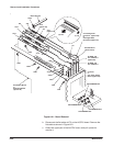
7. Remove A1 Clock board: This circuit board is installed in the fifth slot
from the top.
a. Disconnect the interconnect cables at J300, J400, J410, J420 and
J430 on the A1 Clock board (see Figure 6Ć21).
b. Grasp the upper part of the A1 Clock board and pull upward to
remove it.
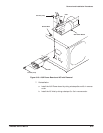
8. Remove A2 AWG board and A11 D/A board (Option 02): The option adds
the A2 AWG board and A11 D/A board in the third slot from the top.
a. Disconnect the interconnect cables at J300 and J400 on the A3
Analog board (see Figure 6Ć21).
b. Disconnect the interconnect cables at the CH3 MARKER OUT and
CH4 MARKER OUT connectors.
c. Grasp the upper part of the A2 AWG board and the A11 D/A board
and pull upward to remove them.
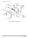
9. Remove A25 Digital Data Out board (Option 04): The option adds the
A25 Digital Data Out board in the first slot from the top.
a. Disconnect the flat cables at J110 and J210 on the A25 Digital Data
Out board (see Figure 6Ć21).
b. Grasp the upper part of the A25 Digital Data Out board, and pull it
upward to remove it.
10. Remove A31 Clock Sweep board (Option 05): This option replaces A1
Clock board with A31 Clock Sweep board.
a. Disconnect the interconnect cables at J300, J360, J400, J410, J420
and J430 on the A31 Clock board (see Figure 6Ć21).
b. Grasp the upper part of the A31 Clock board and pull upward to
remove it.