


Options and Accessories
Options
7Ć6
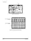
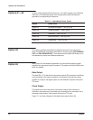
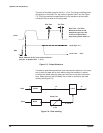
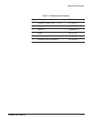
The skew of the data output is held to "15 ns. The rising and falling times
will depend on the buffer ICs, but neither is greater than 4 ns. See Figure
7Ć5. This figure shows the specifications for the waveform at the output
connector when a cable is not being used.
Skew : Measure at 50% level of the waveform :
must be no greater than
"
15 ns.
Level High : 4 V
~
Level Low :
~
0.8 V
Rise Time Fall Time
Rise Time / Fall Time :
Measure the time for the
waveform to go from 10%
to 90% of its peak value ;
must be no greater than 4 ns.
Clock
Data
Figure 7Ć5:ăOutput Waveform
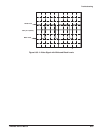
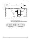
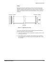
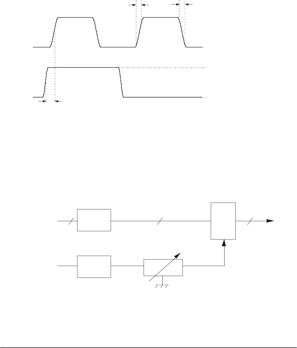
If a cable is used these waveforms have transmission distortion. It is necesĆ
sary to latch the data with a clock before using the waveform in actual
circuits at the cable receiving side (user side) and to reproduce the waveĆ
form. Delay the clock with the delay line in order to reproduce the data
reliably (see Figure 7Ć6).
Buffer
Buffer
Delay Line
12 12 12
Data
Clock
Latch
0
~
20 ns
Figure 7Ć6:ăData Latching