


Removal and Installation Procedures
AWG2005 Service Manual
6Ć13
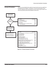
When you have identified the module to be removed for service, read GenerĆ
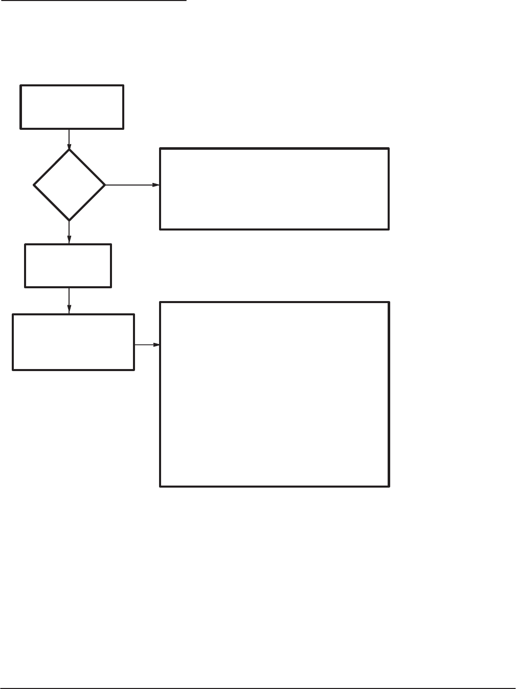
al Instructions found earlier in this section. Then use the flowchart in FigĆ
ure 6Ć2 to determine which procedures to use for removing the module. The
removal procedures end with reinstallation instructions.
Is the
module in
Figure 6Ć3?
Yes
No
Do the procedure, Rear
Cover and Cabinet on
page 6Ć20, removing the
rear cover and cabinet.
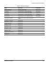
To remove: Go to page:
A23 Analog board or A3 Analog board (Option 02) 6Ć29
Connector Module 6Ć31
Fan and Fan Frame 6Ć33
Rear Shield Cover 6Ć35
Rear BNC Connectors 6Ć37
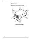
Locate the module to
be removed in
FigureĂ6Ć3 or 6Ć4.
Make sure a floppy
disk is not in the
floppyĆdisk drive.
To remove: Go to page:
FrontĆpanel Knob 6Ć17
Line Fuse and Line Cord 6Ć18
Rear Cover and Cabinet 6Ć20
EMI Gaskets 6Ć22
Front Cover, Trim Ring, and Menu Buttons 6Ć22
FrontĆpanel Module 6Ć24
Power Supply Module 6Ć38
AUX Power Board and AC Inlet 6Ć39
Monitor Module and CRT Frame 6Ć42
A6 CPU, A2 AWG, A11 D/A and A1 Clock board 6Ć45
A2 AWG and A11 D/A board (Option 02) 6Ć45
A25 Digital Data Out board (Option 04) 6Ć45
A31 Clock Sweep board (Option 05) 6Ć45
A7 Floating Point Processor board (Option 09) 6Ć45
A5 Backplane board 6Ć49
Lithium battery 6Ć51
FloppyĆdisk Drive Module 6Ć53
Figure 6Ć2:ăGuide to Removal Procedures
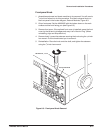
Access Procedure