


Performance Tests
Performance Verification
4Ć36
Flatness 0.15Ădiv., maximum
Fall time 35Ăns, maximum
6. Move the connection for the coaxial cable from the AWG2005 CH1
output to AWG2005 CH2 output connector.
7. Turn on the AWG2005 CH2 output: Push the CH2 button so that the LED
above the CH2 output connector is on.
8. Repeat procedures 4 through 5.
9. If Option 02 is installed (add CH3 and CH4 output channels: Repeat
above procedure for the AWG2005 CH3 and CH4 output channels.
10. End procedure: Remove the connections.
This procedure checks the amplitude of the MARKER OUT signal.
Electrical Characteristic Checked: Auxiliary Output, MARKER, AmpliĆ
tude, on pageĂ1Ć14.
Equipment Required: A 50ĂΩ coaxial cable and an oscilloscope.
Prerequisites: The AWG2005 meets the prerequisites listed on page 4Ć7.
Procedure:
1. Install test hookup and set test equipment controls:
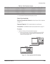
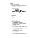
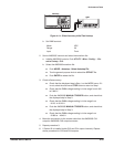
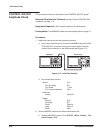
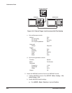
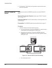
a. Hook up the oscilloscope: Connect the AWG2005 rearĆpanel CH1
MARKER OUT connector through the coaxial cable to the CH1
vertical input connector on the oscilloscope (see Figure 4Ć16).
OscilloscopeAWG2005
AWG2005
Figure 4Ć16:ăInitial Test Hookup
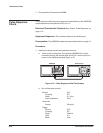
b. Set oscilloscope controls:
MARKER OUT
Amplitude Check