


Options and Accessories
AWG2005 Service Manual
7Ć5
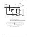
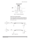
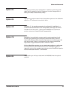
Trigger
Signal
Waveform
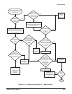
Load, reset, hold–off period:
Excess output can occur in
these periods.
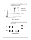
Figure 7Ć3:ăGeneration of Excess Output
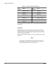
Output Circuit and Output Waveform
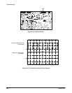
Figure 7Ć4 shows a diagram of the output circuit. After first passing through
an output resistance of 50 Ω, the buffer output proceeds to the output conĆ
nectors. The AWG2005 can be used without terminating the receiving (user)
side with a resistance of 50 Ω, but when waveform distortion is greater the
50 Ω termination is required.
( 50
W )
50
W
Buffer
( 50
W )
50
W
Buffer
Figure 7Ć4:ăOutput Circuit