Removal and Installation Procedures
AWG2005 Service Manual
6Ć25
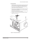
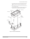
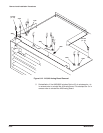
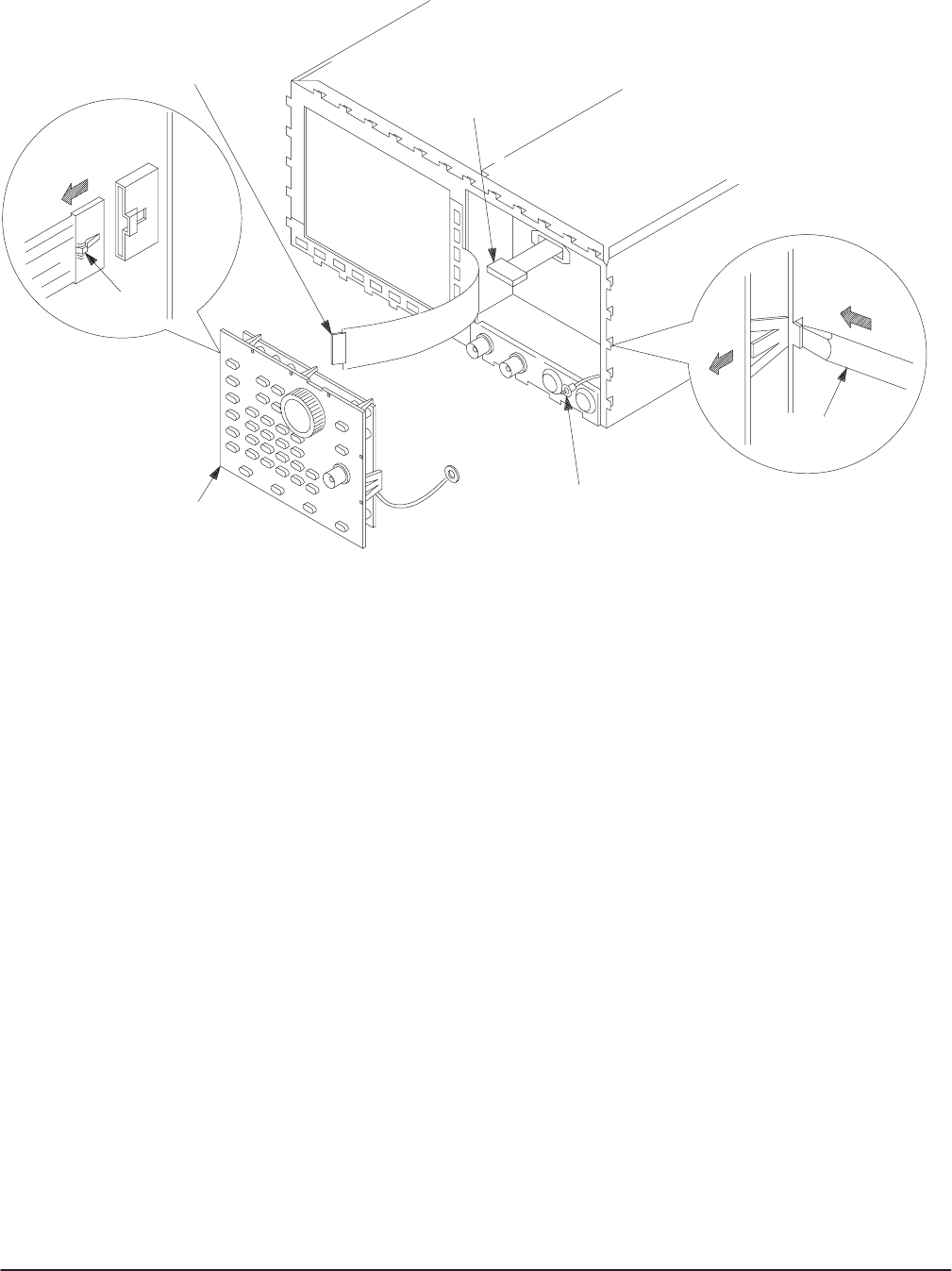
To J101
To JP301
Front-panel
Module
(2)Pull
(1)Push
Flat-bladed
Screwdriver
To TRIGGER
INPUT Connector
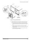
Figure 6Ć9:ăFrontĆpanel Module Removal
6. Further disassembly of frontĆpanel module: If the frontĆpanel module or
the frontĆpanel buttons are to be serviced, do the following substeps:
a. Remove the frontĆpanel knob from the frontĆpanel module using the
method described in the procedure, FrontĆpanel Knob, on page
6Ć17.
b. Remove the setscrew completely from the extension using the
0.05Ćinch hex wrench, and then remove the extension from the shaft
of the rotary switch.
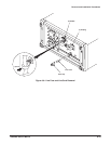
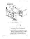
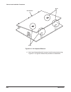
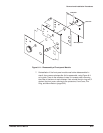
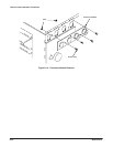
c. As shown in Figure 6Ć10, release the four hooks, and then remove
the A12 Keyboard from the chassis.


