


Removal and Installation Procedures
Maintenance
6Ć28
Do the Access Procedure (on page 6Ć13) before doing any procedure in this
group.
This part contains the following removal and installation procedures; the
procedures are presented in the order listed:
H A23 Analog Board or A3 Analog Board (Option 02)
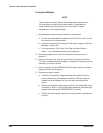
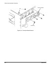
H Connector Module
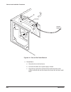
H Fan and Fan Frame
H Rear Shield Cover
H Rear BNC Connector
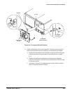
H Power Supply Module
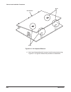
H AUX Power Board and AC Inlet
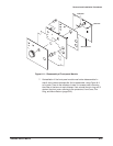
H Monitor Module and CRT Frame
H Circuit Boards:
H A6 CPU Board
H A2 AWG Board
H A11 D/A Board
H A1 Clock Board
H For Option 02: A2 AWG Board and A11 D/A Board
H For Option 04: A25 Digital Data Out Board
H For Option 05: A31 Clock Sweep Board
H For Option 09: A7 Floating Point Processor Board
H A5 Backplane Board
H Lithium Battery
H Floppy Disk Drive Module
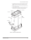
Procedures for
Internal Modules