


Options and Accessories
Options
7Ć2
In place of the standard North American, 110ĂV, 60ĂHz power cord, Tektronix
ships any of five alternate power cord configurations with the waveform
generator, as ordered by the customer.
TableĂ7Ć1:ăInternational Power Cords
Option
Power Cord
Option A1 Universal European Ċ 220ĂV, 50ĂHz
Option A2 United Kingdom Ċ 240ĂV, 50ĂHz
Option A3 Australian Ċ 240ĂV, 50ĂHz
Option A4 North American Ċ 240ĂV, 60ĂHz
Option A5 Switzerland Ċ 220ĂV, 50ĂHz
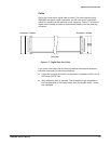
This option provides two additional channels (channel 3 and channel 4).
Also, two additional connectors are added on the rear panel (CH3 MARKER
OUT and CH4 MARKER OUT). The instrument with Option 02 allows you to
simultaneously output four different waveforms.
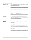
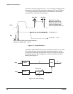
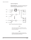
With Option 04, the waveform generator can provide the following digital
signals at the rear panel output connector. This option and Option 09 cannot
both be installed.
Data Output
The data (D0-D11) fed to this instrument's internal D/A converter is buffered
and connected to the output connector. At the same time that the analog
waveform is output, the digital output can be obtained. Output will be at the
TTL level.
Clock Output
The same clock that is fed to this instrument's internal D/A converter is
buffered in the same way as the data and connected to the connector. As in
the case of data output, clock output will be at the TTL level.
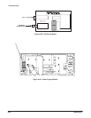
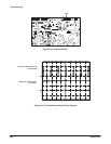
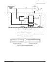
Figure 7Ć1 is a block diagram of the digital data output Option 04.
Options A1-A5
Option 02
Option 04