


Removal and Installation Procedures
Maintenance
6Ć46
)
A2 AWG and
A11 D/A Board
(1) Up
(2) Pull
CH2 MARKER OUT
J110
(Option 04)
J430
J400
J410
J420
A23 Analog Board
or
A3 Analog Board
(Option 02)
CH1 MARKER OUT
J300
J200
J100
A1 Clock
or
A31 Clock Sweep
Board (Option 05)
CH4 MARKER OUT
J210
J300
J110
J110
J360
J400
Hook
Board Support
J50
J64
J210
(Option 04)
J210
J75
J30
A7 Floating Point
Processor (Option 09)
or
A25 Digital Data
Out Board (Option 04)
A6 CPU Board
(Second Slot)
A2 AWG and
A11 D/A Board
(Option 02)
CH3 MARKER OUT
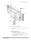
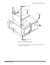
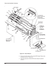
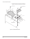
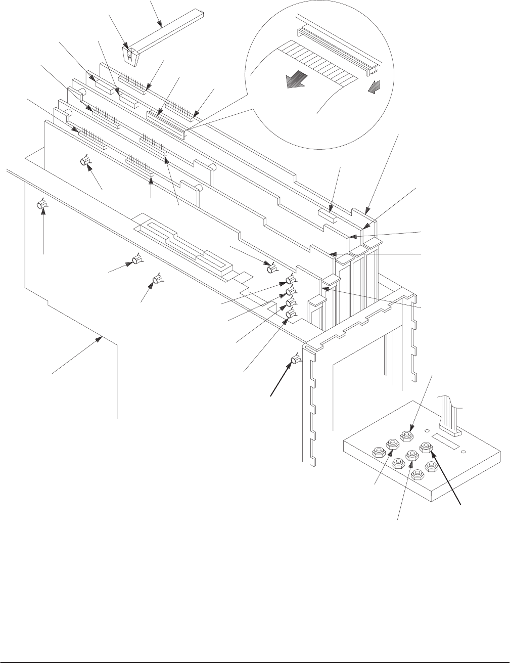
Figure 6Ć21:ăBoard Removal
b. Disconnect the flat cable at J75 on the A6 CPU board. Remove the
flat cable as shown in Figure 6Ć21.
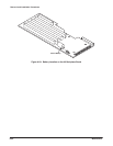
c. Grasp the upper part of the A6 CPU board, and pull upward to
remove it.