


Characteristics
Specifications
1Ć8
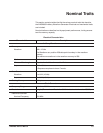
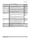
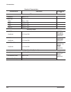
Electrical Characteristics
Characteristics Description
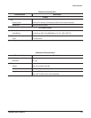
Auxiliary Input
TRIGGER
Threshold Level -5 V to 5V
Resolution 0.1V
Impedance 10kW
AM
Range 2 VpĆp (-1V to 1V) for 100% modulation
Impedance 10kW
Add
Range 10 VpĆp (-5 V to 5V)
Impedance 50W
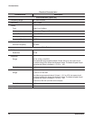
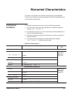
CONTROL SIG
Threshold Level 0.8 V to 2.0 V
Impedance 10kW
CLOCK
Threshold Level 0.8 V to 2.0 V
Impedance 330W (Master mode), 10kW (Slave mode)
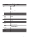
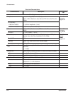
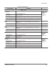
Function Generator
Waveform Shape Sine, Triangle, Square, Ramp, Pulse
(1 MHz filter is inserted when Sine is selected.)
Output Parameter All of these values with the exception of frequency can be set indepenĆ
dently for each channel. Frequency settings apply to all channels.
Frequency 1.000 Hz to 200 kHz
Amplitude Can be set between 50 mV and 10 V in 1 mV increments
Offset
Can be set between "5 V in 5 mV increments
Polarity Normal, Invert
Duty 0% to 100% Pulse only. Can be set in 1% increments
Operating Mode Continuous mode
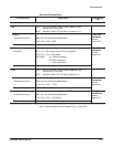
Auxiliary Output
Marker 2V into 50W, generated at the starting point of the waveform. The pulse
width will vary depending on the frequency.