U41117-J-Z125-7-76 129
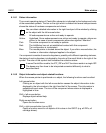
GXCC Main window
Fibre channel elements
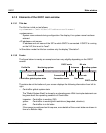
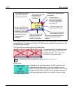
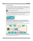
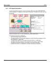
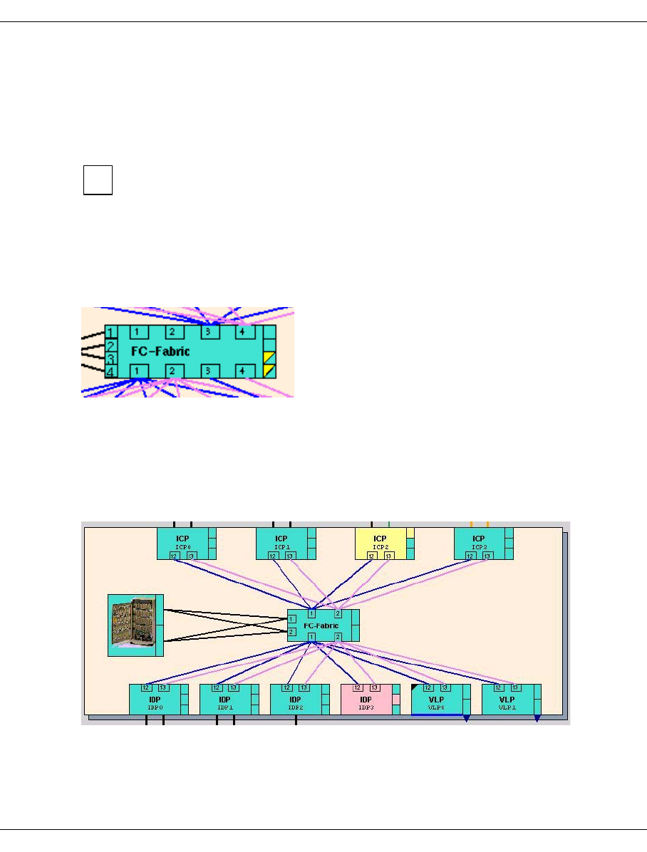
The internal FC connections are represented in the form of an FC fabric in the center of the
figure with connections to both the ISPs and the RAID system(s). FibreChannel connec-
tions to the FC switch which are faulty are drawn with dashed lines until the SNMP trap has
been processed by the FC switch. These lines are then removed.
The VLP and the SVLP must be entered in the FC switch as the trap receiver, oth-
erwise the lines cannot be removed.
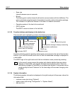
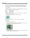
Each FC switch is symbolized by a box containing the domain number located at the edge
of the fabric. As the image on the right shows, a switch can be shown twice, once at the
upper edge and once at the lower edge of the fabric. This means that the connections can
be seen more clearly, although this bears no relevance on the function.
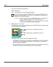
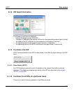
In the figure below the switches with the domain numbers 3 and 4 have reported a trap:
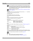
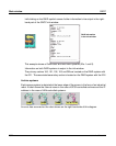
Some of the CentricStor components shown (e.g. the Fibre Channel switches) are
monitored with SNMP. If a message (=trap) from one of these components which no
management station has yet taken notice of is present, a circle highlighted in yellow with
the text “SNMP” appears in the button bar of the GXCC window.
The LAN via which the control of the system and communication with the InfoBroker runs
in CentricStor is not displayed in GXCC.
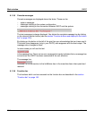
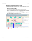
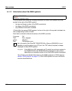
GXCC checks whether the internal CentricStor FC fabric complies with the cabling rules.
If the rules have been violated, a warning symbol (gears) is displayed in the button bar.
The incorrect connections are displayed in red.
i


