


AW1600 Owner’s Manual
Parts of the AW1600 and what they do
2
Introducing the AW1600
22
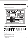
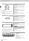
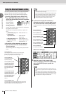
F USB Connector
This connector allows the unit to be directly connected to
a USB-equipped computer via a standard USB cable
(compatible with USB 2.0). When the USB Storage mode
is selected WAV files and song files can be transferred
between the AW1600 and the computer. In the “normal”
mode the USB connection can be used for MIDI control.
The USB interface does not directly handle audio signals.
G DIGITAL STEREO IN/OUT jacks
These jacks allow direct transfer of digital audio between
the AW1600 and DAT recorders, MD (MiniDisc) record-
ers, CD recorders, and other consumer-format digital
audio gear. These connectors conform to the IEC-60958
standard.
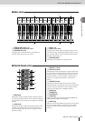
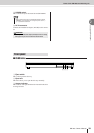
H FOOT SW jack
A separately sold foot switch (Yamaha FC5) can be con-
nected here to control transport operations such as start/
stop, or to perform punch-in/out.
I MIDI IN connector
J MIDI OUT/THRU connector
These connectors allow MIDI messages to be exchanged
with external devices.
MIDI IN receives MIDI messages.
MIDI OUT/THRU can be internally switched to function
either as a MIDI OUT jack (which transmits MIDI mes-
sages generated within the AW1600) or MIDI THRU jack
(which re-transmits messages that are received at the
MIDI IN jack).
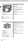
K PHANTOM +48V CH1–4 and CH5–8 Switches
Independent phantom power switches are provided for the
XLR-type MIC/LINE INPUT connector groups 1 through
4 (CH1–4) and 5 through 8 (CH5–8). Turn phantom power
to the appropriate connectors ON when using one or more
phantom-powered condenser microphones.
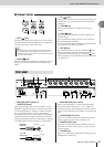
L Ground Screw
For maximum safety the ground screw should be properly
connected to a confirmed ground point. Proper grounding
will also ensure minimum hum, noise, and interference.
Caution when using the USB connector
You must observe the following points when con-
necting the AW1600 to your computer via the USB
connector. If you fail to observe these points, your
computer or the AW1600 may stop operating (“hang
up”), causing data to be corrupted or lost. If the
computer or the AW1600 stops working, turn the
power off and then on again, and restart the com-
puter.
• Before connecting the computer via the USB con-
nector, disable the power management mode
(suspend/sleep/standby/hibernate) on your com-
puter.
• Connect the USB connector to the computer
before you power-on the AW1600.
•Execute the following before turning the power to
the AW1600 on/off, connecting/disconnecting the
USB cable, or turning the USB Storage mode on/
off.
• Close all application programs.
• If the USB Storage mode is off, make sure that data
is not being transmitted from the AW1600.
• If the USB Storage mode is engaged, make sure
that reading and writing files is not in progress.
• If the USB Storage mode is engaged, safely remove
the AW1600 from the Windows taskbar or drag the
AW1600 icons from the Macintosh desktop to the
trash after closing all AW1600 windows.
• Leave an interval of at least six seconds between
powering the AW1600 on and off, or between dis-
connecting and connecting the USB cable.
• The USB interface cannot be directly connected to external hard
disks or CD-R/RW drives.
• The AW1600 can be connected to either a USB 2.0 or USB 1.1
interface, but data transfer will be slower if a USB 1.1 interface is
used.
• When connecting via USB 2.0 be sure to use a cable specified for
USB 2.0 use.
• The USB MIDI driver provided on the supplied CD-ROM must be
properly installed to allow MIDI message transmission and recep-
tion.
• When connecting USB cables, make sure to connect the AW1600
directly to a computer without USB hub.
NOTE
• The appropriate operation may not occur if you use a foot switch
other than the Yamaha FC5 (or equivalent).
• Does not function when the MTC MODE is “SLAVE” or while the
REW[ ], FF[ ], or [JOG ON] key is being used.
• When a record track is assigned in the RECORD screen the func-
tions are switched in the following order: PLAY[ ] → Punch In
→ Punch Out → STOP[
■
]. When Auto Punch-in/Out is engaged,
however, the order becomes Punch In → STOP[
■
].
NOTE
• Be sure to turn the phantom power switches off when phan-
tom power is not required.
• Make sure that no equipment other than phantom-powered
microphones is connected to the XLR inputs of the input
group for which phantom power is turned on. Applying phan-
tom power to devices that are not phantom-powered can
cause damage. Balanced dynamic microphones, however,
can usually be connected without adverse effect.
•To prevent speakers damage turn power amplifiers (or pow-
ered speakers) off when switching phantom power on or off.
It’s also a good idea turn all master faders and output volume
controls down to minimum. The noise generated when phan-
tom power is switched on or off can damage system compo-
nents and may even cause hearing damage if amplified to
sufficiently high levels.
CAUTION