


Hardware Initialization States
3-21
Peripheral Functions
Note: Stack Pointer Initialization
The software stack pointer (R7) must be initialized by the programmer, so
that it points to some legitimate address in data memory (RAM). This must
be done prior to any CALL or C
CC
instruction. If this is not done, then the first
push/pop operation performed on the STACK will render the Program Count-
er to an unknown state.
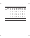
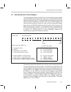
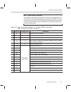
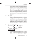
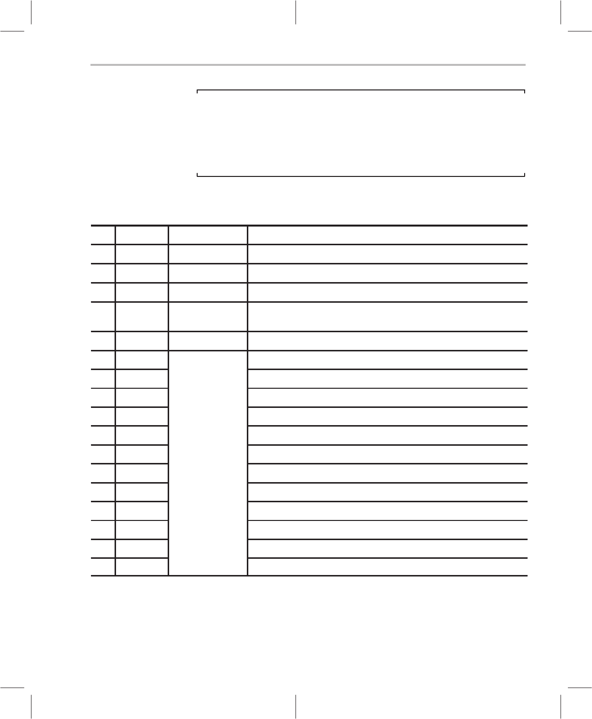
Table 3–2. State of the Status Register (17 bit) after RESET Low-to-High
(Bits 5 through 16 are left uninitialized)
Bit Bit Name Initialized Value Description
0 XM 0 Extended sign mode disabled
1 UM 0 Unsigned multiplier mode disabled (allows signed multiplier mode)
2 OM 0 Overflow mode disabled (allows ALU normal mode)
3 FM 0
Shift mode for fractional multiplication disabled (allows unsigned
fractional/integer arithmetic)
4 IM 0 Global interrupt enable bit
5 (reserved) Reserved for future use
6 XZF Transfer equal-to-zero status bit
7 XSF Transfer sign status bit
8 RCF Auxiliary register carry-out status bit
9 RZF Auxiliary register equal-to-zero status bit
10 OF
Same state as
Accumulator overflow status bit
11 SF
before RESET
Accumulator sign status bit (extended 17th bit)
12 ZF Accumulator equal-to-zero status bit (16 bits)
13 CF Accumulator carry-out status bit (16th ALU bit)
14 TF1 Test flag 1
15 TF2 Test flag 2
16 TAG Memory tag