


MSP50C614/MSP50P614 Initialization Codes
6-4
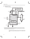
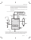
In any C614 application, it is important for certain components to be located
as close as possible to the C614 die or package. These include any of the
decoupling capacitors at V
DD
(0.1 µF). It also includes all of the components
in the crystal-reference network between OSC
IN
and OSC
OUT
(22 pF, 10 MΩ,
32 kHz).
6.2 MSP50C614/MSP50P614 Initialization Codes
Before any kind of application code can be written, the MSP50C614/
MSP50P614 processor state must be initialized. The initialization code is in-
it.asm, where file extension .asm is for an assembly language file.
The entry point to the initialization routine is INIT_DEVICE_614. This entry
point
must not
be called (call INIT_DEVICE_614). A
jump
to this routine should
be used (jmp INIT_DEVICE_614). After the end of initialization, the routine
always jumps to the _main, which is the beginning of MSP50P614/
MSP50C614 user code. It is recommended that INIT_DEVICE_614, is per-
formed immediately after RESET to ensure that device initialization is always
performed at RESET. Users modifying the initialization routine is not recom-
mended.
The initialization routine does the following:
Disables all interrupts.
Zeros out all accumulators.
Zeros out all memory.
Starts oscillators at frequency 8.192 MHz. If CRO_FLAG is 1, then crystal
oscillator is started. If CRO_FLAG is 0, then the resistor trim oscillator is
started. If resistor trim oscillator is chosen in P614 part, then RESISTOR-
TRIM must be defined by the user (this value is written under the P614
part). If the C614 part is used, then the resistor trim is read from I/O location
RTRIM (0x2F).
Delays execution of the core for 200 ms for PLL to stabilize.
Zeros out system registers.
Finally jumps to the label _main.
WARNING
If P614 parts are used for development, then the user MUST
CHANGE the resistor trim initialization to read from port 0×2F when
switching to the C6xx part.