


I/O
3-4
3.1.2 Dedicated Input Port F
Port F is an 8-bit wide input-only port. The data presented to the input pin can
be read by referring to the appropriate bit in the F port data register, address
0x28. This is done using the IN instruction, with the 0x28 address as an
argument. The state of the F port data registers after RESET low is unknown
(input state provided by external hardware)
Each of the pins at port F has a programmable pull-up resistor. The resistance
of these pullups is at least 100 kΩ. All eight pullup resistors can be enabled by
setting the enable pullup (EP) in the interrupt/general control register (Int-
GenCtrl). The address of the IntGenCtrl is 0x38, and the location of the EP bit
is 12. Clearing the EP bit disables the eight pullups, and setting the EP bit en-
ables the eight pullups. After RESET low, the default setting for the EP bit is
0 (F-port pullups disabled).
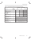
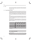
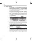
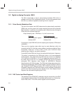
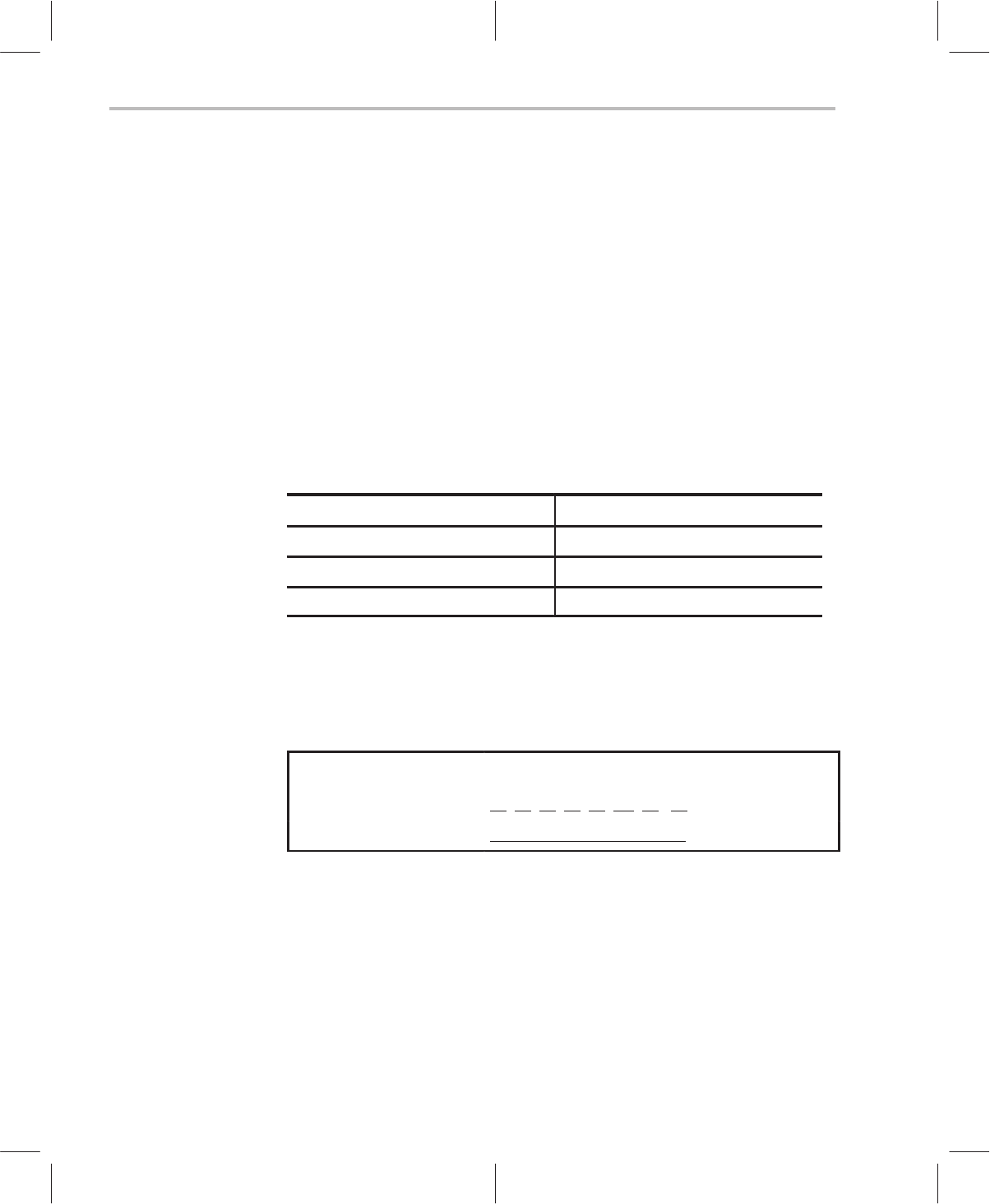
Input Port F
Data register address
0x28h
Possible input data values Low = 0 High = 1
Possible output data values N/A
Value after RESET low Pullup resistors DISABLED
When reading from the 8-bit F-port data register to a 16-bit accumulator, the
IN instruction automatically clears the extra bits in excess of 8. The desired bits
in the result will be right-justified within the accumulator.
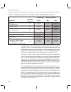
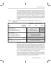
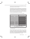
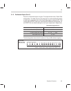
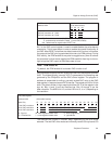
The following table shows the bit locations of the port F address mapping:
F port Input Data register
address 0x28h
READ only
(8-bit wide location)
07
06 05 04 03 02 01 00
F7 F6 F5 F4 F3 F2 F1 F0
The external interrupt INT5 is triggered by a falling-edge event on any of the
eight port-F input pins (see Section 3.1.5,
Internal and External Interrupts
).
Specifically, INT5 is triggered if all eight port-F pins are held high, and then one
or more of these pins is taken low. Port F, therefore, is especially useful as a
key-scan interface.