2-3
MSP50C614 Architecture
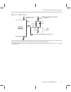
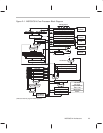
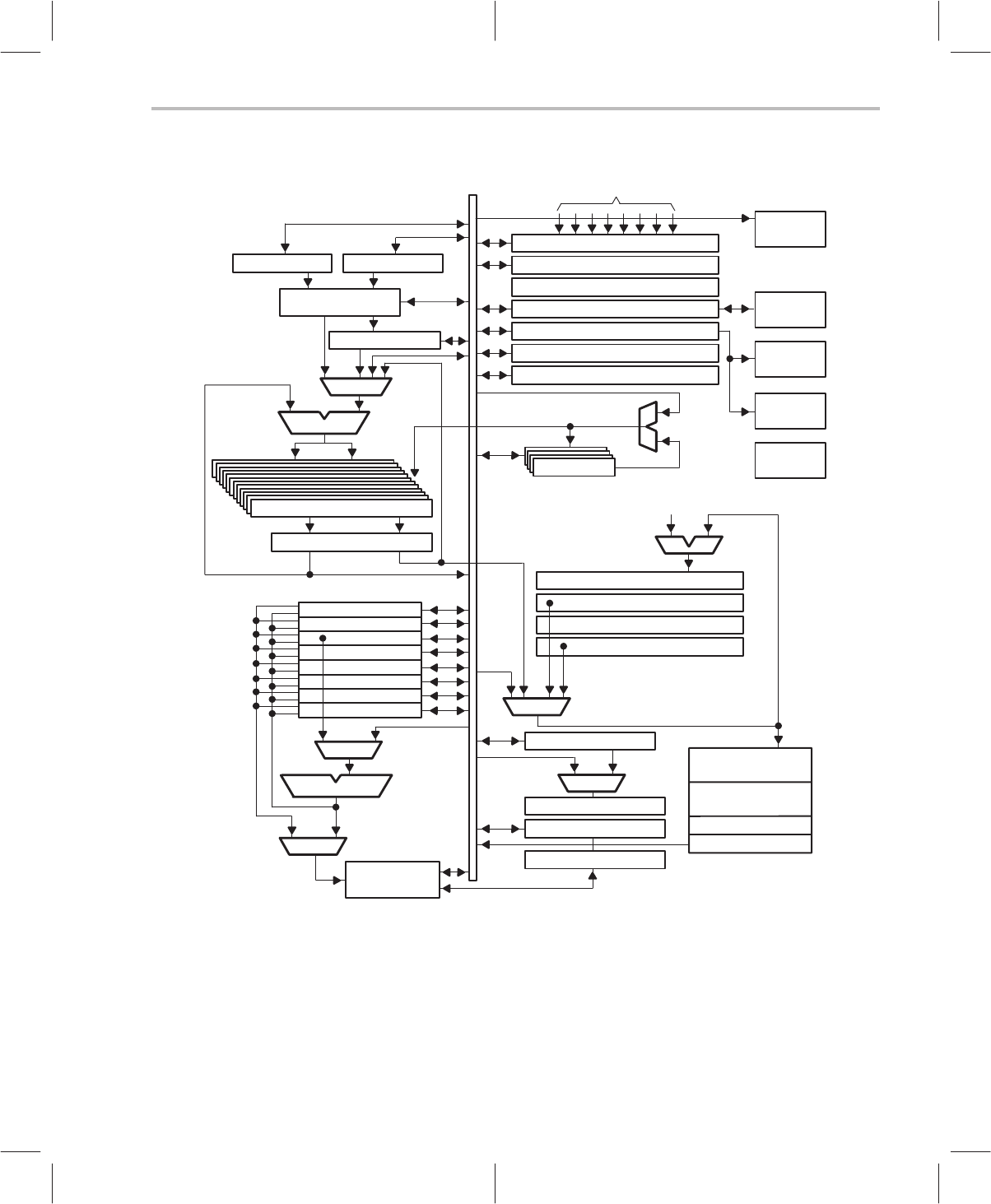
Figure 2–1. MSP50C614 Core Processor Block Diagram
Multiplier (MR)† Shift Value (SV)†
17 x 17 Multiplier
Product High (PH)†
16 bit ALU
MUX
32 Accumulators (AC0–AC31)†
Column Exchange
Loop (R4)
Index (R5)
Page (R6)
Stack (R7)
R0
R1
R2
R3
Arithmetic Unit
MUX
MUX
Data Memory
640 x 17 bit
Interrupt Flag Register (IFR)†
Control Register (CTRL)†
Interrupt Inputs
Interrupt Processor
Serial Interface Register†
Oscillator Register†
Timer Period (PRD1 and PRD2)†
Timer Register (TIM1 and TIM2)†
AP0–AP3†
Accumulator Pointer
Incrementor
+1
Peripheral
Interface
Instruction
Decoder
Frequency
Divider
VCO
Serial
Interface
Top Of Stack (TOS)†
Program Counter (PC)†
Protection Register (PR)†
Data Pointer (DP)†
MUX
String Register†
MUX
Repeat Counter†
Status Register (STAT)†
Flag Register†
Vectors
Macro Calls
Program Memory
30k x 17 bit
Test Code
2k x 17 bit
†
Indicates internal programmable registers.


