Bit, Byte, Word and String Addressing
4-47
Assembly Language Instructions
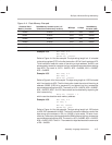
Figure 4–4. Data Memory Example
Absolute Word
Memory Location
Data Memory Location (even) = 2 *
(Absolute word memory location)
MS Byte LS Byte
Data Memory
Location (odd)
0x0000
0x0000 0x12 0x34 0x0001
0x0001 0x0002 0x56 0x78 0x0003
0x0002 0x0004 0x9a 0xbc 0x0005
0x0003 0x0006 0xde 0xf0 0x0007
0x0004 0x0008 0x11 0x22 0x0009
0x0005 0x000a 0x33 0x44 0x000b
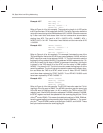
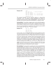
Example 4.5.4 MOV STR, 4–2
MOV AP0, 2
MOVBS A0, *0x0003
Refer to Figure 4–4 for this example. The byte-string length is 4. It is loaded
to the string register (STR) in the first instruction. AP0 is 2 and it points to AC2.
Third instruction loads the value of the string at byte address, 0x0003, and
subsequently stores its contents into four consecutive accumulators starting
from AC2. The result is, AC2 = 0x0078, AC3 = 0x009A, AC4 = 0x00BC,
AC5 = 0x00DE.
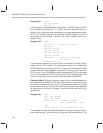
Example 4.5.5 MOV STR, 4–2
MOV AP0, 2
MOVS A0, *0x0003
Refer to Figure 4–4 for this example. The byte-string length is 4. AP0 is loaded
with 2 and points to AC2. The third instruction loads the value of the string at
address 0x0002 (LSB bit is assumed 0) and stored into four consecutive
accumulators starting from AC2. The result is, AC2 = 0x5678, AC3 = 0x9ABC,
AC4 = 0xDEF0, AC5 = 0x1122. Same result can be obtained by replacing the
third instruction by,
MOVS A0, *0x0001 * 2
which uses the absolute word memory address.
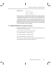
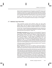
Example 4.5.6 MOV STR, 4–2
OV AP0, 2
MOV R0, 0x0005
MOVBS A0, *R0++
Refer to Figure 4–4 for this example. The byte string length is 4. AP0 points
to AC2. R0 is loaded with 0x0005. The fourth instruction loads the value of the
byte-string at the address in R0 (i.e, 0x0005 in byte mode). R0 auto–incre-
ments by 1 after every fetch and stores the RAM contents into four consecutive
accumulators starting from AC2. The result is, AC2 = 0x00BC, AC3 = 0x00DE,
AC4 = 0x00F0, AC5 = 0x0011. There were four byte fetches and the new value
of R0 = 0x0009.


