


MSP50C614/MSP50P614 Initialization Codes
6-6
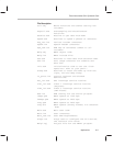
out IntGenCtrl,a0 ;clear all interrupt mask bits, disable
timers
mov r0,0x000 ;point to beginning of RAM
mov r4,RAM_SIZE – 2 ;do a loop RAM_SIZE times
BEGLOOP
rtag *r0 ;reset tag
mov *r0++,a0 ;clear the RAM
ENDLOOP
mov STR,0 ;clear string register
mov ap0,0 ;clear accum pointer 0
mov ap1,0 ;clear accum pointer 1
mov ap2,0 ;clear accum pointer 2
mov ap3,0 ;clear accum pointer 3
mov r0,0 ;clear register 0
mov r1,0 ;clear register 1
mov r2,0 ;clear register 2
mov r3,0 ;clear register 3
mov r4,0 ;clear register 4
mov r5,0 ;clear register 5
mov r6,0 ;clear register 6
mov r7,0 ;clear register 7
mov sv,0 ;clear shift value register
mov TOS,*0x000 ;clear top of stack register
mov PH,*0x000 ;clear product high register
mov MR,*0x000 ;clear multiplier register
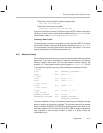
;****************************************************************
; Choose the source for the reference oscillator. Set the PLLM
; register accordingly (in this case for a CPU clock of 8 MHz)
; and then set TIMER 2 to a 200 ms period.
; Go to sleep (do an IDLE) and wake up when the clock has
; reached full speed and is stable.
;****************************************************************
#if CRO_FLAG
mov a0,CROENABLE ;enable crystal oscillator
#else
#if C614_FLAG
in a0,RTRIM ;for C614 read trim value from register
#else
mov a0,RESISTORTRIM ;for P614 the user supplies the trim value
#endif
and a0,0x3f ;only want lower 6 bits
mov a0~,a0 ;save a copy for later
mov sv,10 ;need to shift left by 10
shltpl a0,a0 ;bit 1 is now bit 11, bit 0 now bit 10
or a0,RTOENABLE ;enable resistor–trimmed oscillator
and a0,~IDLEBIT ;clear bit 10
; 6 bit trim resides in bits 15–11 and bit 9 (LSB of trim value)
and a0~,a0~,0x01 ;look at bit 0 of trim value
jz trimbit0 ;do nothing if it is zero
or a0,0x0200 ;else set bit 9
trimbit0
#endif
orb a0,PLLMBITS ;set PLLM for CPU clock of 8 MHz