Instruction Syntax and Addressing Modes
4-11
Assembly Language Instructions
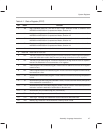
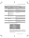
Table 4–5. MSP50P614/MSP50C614 Addressing Modes Summary
ADDRESSING SYNTAX OPERATION
Direct
name [dest,] [src,] *dma16 [*2] [, next A]
name *dma16 [*2] [,src] [, next A]
Second word operand (
dma16
) used directly as memory
address.
Long Relative
name [dest] [,src] ,
*R
x
+
offset16 [, next A]
name
*Rx+
offset16 [,src] [, next A]
Selects one of 8 address registers as base value and adds
the value in the second word operand. Does not modify the
base address register.
Relative to R5
(INDEX)
name [dest] [,src] ,
*R
x+R5 [, next A]
name
*Rx+R5
[,src] [, next A]
Selects one of 8 address registers as base value and adds
the value in R5. Does not modify the base address register.
Indirect
name [dest] [, src] ,
*Rx
++R5 [, next A]
name [dest] [, src] ,
*Rx
[, next A]
name [dest] [, src] ,*Rx++ [, next A]
name [dest] [, src] ,*
R
x— [, next A]
name
*Rx++R5
[, src] [, next A]
name
*Rx
[, src] [, next A]
name
*Rx++
[, src] [, next A]
name
*Rx––
[, src] [, next A]
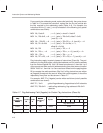
Selects one of 8 address registers to be used as the ad-
dress, post modifications of increment, decrement, and +
INDEX(R5) are possible.
Short Relative
name [dest] [, src] ,*R6+offset7 [, next A]
name
*R6+
offset7 [, src] [, next A]
Selects PAGE(R6) register as the base address and adds a
7 bit positive address offset from operand field (b6–b0). This
permits the relative addressing of 128 bytes or 64 words.
Does not modify the PAGE address register.
k
is shown as
constant.
Global Flag
name
TF
n, dma6
name dma6, TFn
For use with flag instructions only. Adds lower 7 bits of
instruction to a fixed address base reference of zero. 64
fixed flags are addressed by this mode beginning at ad-
dress 0000h.
Relative Flag
name
TF
n,
*R6+
offset6
name
*R6+
offset6,
TF
n
For use with flag instructions only. Adds lower 7 bits of
instruction(lsb set to zero) to a address base reference
stored in the PAGE register (R6). 64 flags relative to PAGE
may be addressed with this mode.
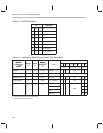
Table 4–6. Auto Increment and Auto Decrement Modes
Operation Syntax
next A
No modification 0 0
Aufto increment ++A 0 1
Auto decrement ––A 1 0
String mode 1 1
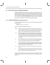
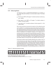
Table 4–6 describes the accumulator pointer auto preincrement or
predecrement syntax. Not all instructions can premodify accumulator pointers.
The
next A
field is a two bit field using bits 10 and 11 of only certain classes
of instructions. Instructions with a [
next A
] have either a ––A or a ++A in the
instruction. See Table 4–6.


