


Comparator
3-15
Peripheral Functions
bit is automatically CLEARed again if an INT6 event occurs at the same time
that the associated mask bit is SET (IntGenCtrl, address 0x38, bit 6). The latter
indicates that the program vectoring associated with INT6 is enabled. (The flag
bit is SET when the INT event occurs. Only if the mask bit is set, does the
interrupt service occur: vectoring takes place and the flag bit is once again
cleared. Refer to Section 2.7,
Interrupt Logic
, for more details)
The INT6 Flag may also be SET or CLEARed deliberately, at any time, in
software. Use the OUT instruction with the associated I/O port address (IFR,
address 0x39).
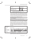
INT7 flag refers to bit 7 within the interrupt flag register. This bit is automatically
SET anytime that an INT7 event occurs. The bit is automatically CLEARed
again if an INT7 event occurs at the same time that the associated mask bit
is SET (IntGenCtrl, address 0x38, bit 7). The latter indicates that the service
for INT7 is enabled.
The INT7 Flag may also be SET or CLEARed at any time, in software. Use the
OUT instruction with the associated I/O port address (IFR, address 0x39).
The TIMER1 enable bit is set or cleared in software: bit 10 of the IntGenCtrl.
Similarly, the
falling
-edge event in the comparator is a trigger for INT7. This
happens independently of any activity associated with TIMER1. TIMER1
starts
counting anytime the following conditional is true:
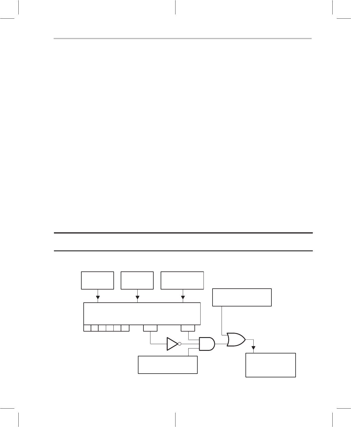
IF: [(INT6 Flag is CLEAR) AND (INT7 Flag is SET)] OR (TIMER1 Enable is SET)]
THEN: TIMER1 starts counting
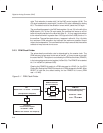
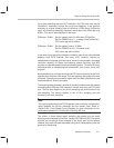
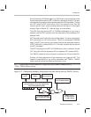
Figure 3–2. Relationship Between Comparator/Interrupt Activity and the TIMER1 Control
INT Flag bits (IFR)
Associated With the Interrupt-Trigger Event
Interrupt Flag Register (0x39)
0 1 2 3 4 5 INT6 INT7
INT-Trigger
Event
INT Service
Branch
port-addressed
write instruction
Comparator ENABLE
Bit 15, IntGenCtrl (0x38)
TIMER1 ENABLE
Bit 10, IntGenCtrl (0x38)
TIMER1 Control
0 = TIM1 stopped
1 = TIM1 running