


Clock Control
2-30
The maximum required CPU clock frequency for the C614 is 8 MHz over the
entire V
DD
range. This rate applies to the speed of the core processor. Higher
CPU clock frequencies may be achieved, but these are not qualified over the
complete range of supply voltages in the guaranteed specification.
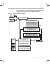
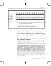
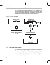
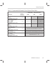
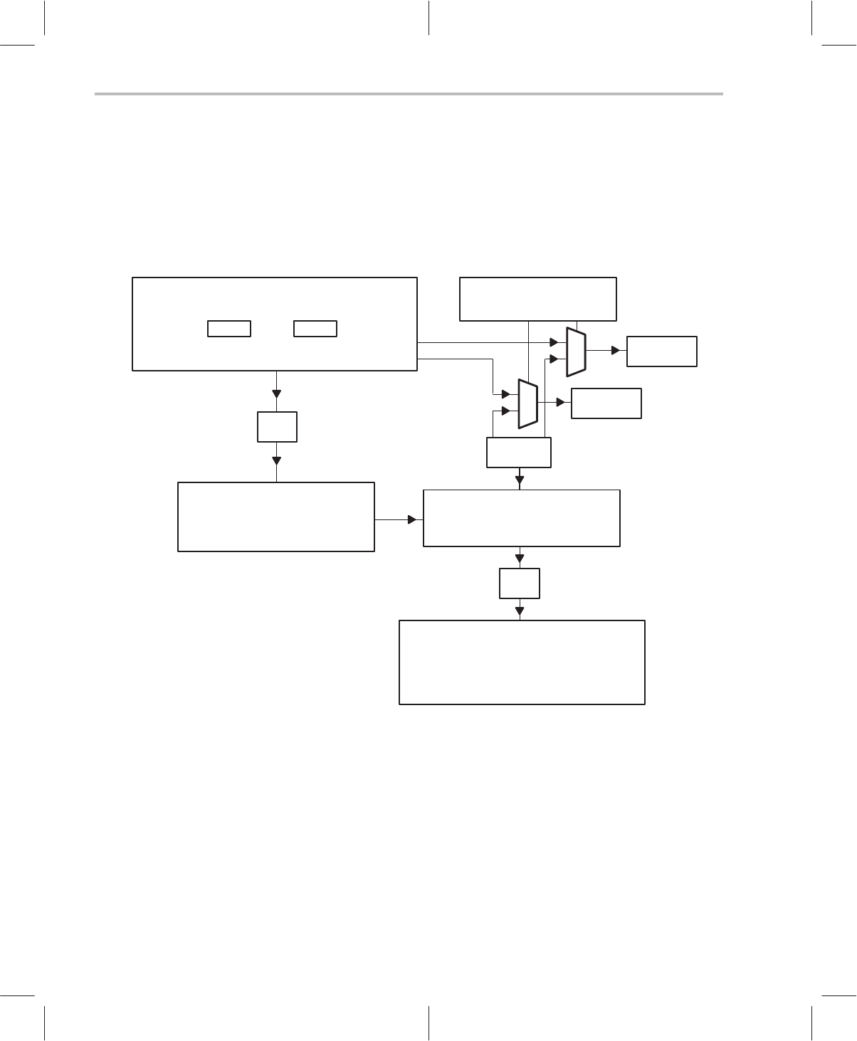
Figure 2–9. PLL Performance
Oscillator Reference
32 kHz
RTO CRO
Selection Made in ClkSpdCtrl
crystal
referenced
Resistor
Trimmed
or
PLL
Phase-Locked-Loop circuit
Multiplier Adjusted in ClkSpdCtrl
x 1 ... x 256
x4
Timer Source Option
Selected in IntGenCtrl
1
0
TIMER2
1
0
TIMER2
÷2
MC
Master Clock : Runs Periphery
131.07 kHz ... 33.554 MHz
÷2
CPU Clock
Core-Processor Speed
65.536 kHz ... F
MAX
(F
MAX
= 8 MHz)
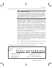
2.9.3 Clock Speed Control Register
The ClkSpdCtrl is a 16-bit memory mapped register located at address 0x3D.
The reference oscillator (RTO or CRO) is selected by setting one of the two
control bits located at bits 8 and 9. Setting bit 8 configures the C614 for the RTO
reference option and simultaneously starts that oscillator. Setting bit 9
configures the C614 for the CRO reference option and simultaneously pulses
the crystal, which starts that oscillator.