Reduced Power Modes
2-38
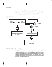
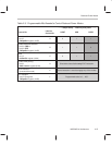
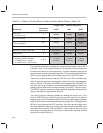
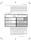
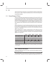
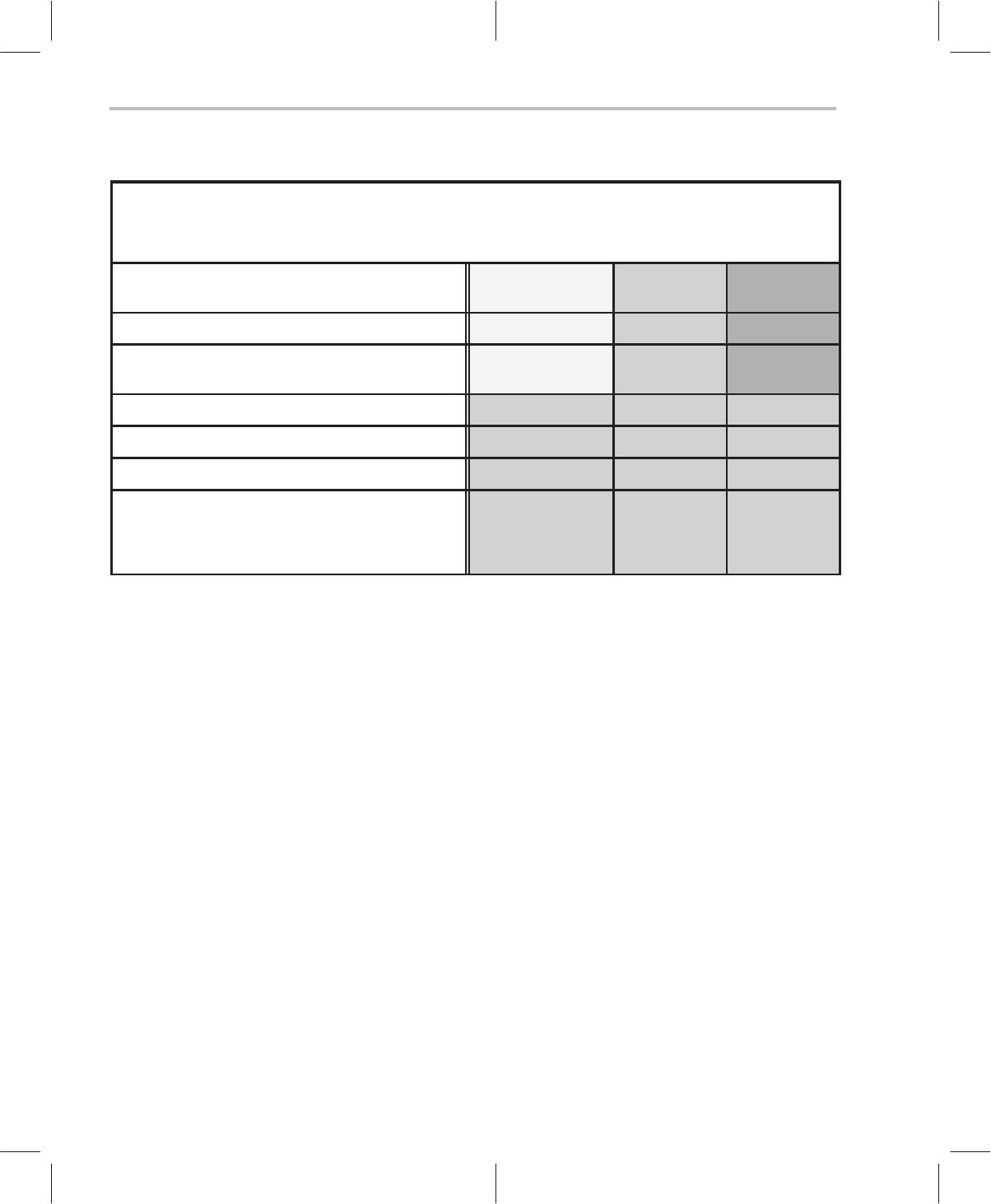
Table 2–4. Status of Circuitry When in Reduced Power Modes (Refer to Table 2–3)
→ deeper sleep … relatively less power →
Component
Determined
by Controls
LIGHT MID DEEP
CPU clock
(processor core)
E stopped stopped stopped
PLL clock circuitry A, E running stopped stopped
Master clock (MC) status
(C614 periphery)
A, E running stopped stopped
MC rate B, F 131 kHz … 34 MHz — —
Synchrony of external interrupts C, E Synchronous Asynchronous Asynchronous
PDM pulsing D stopped stopped stopped
TIMER1 or TIMER2 status
• Assuming TIMER is enabled
1) TIMER source = 1/2 MC
2) TIMER source = RTO or CRO
A, B, E
1) running
2) running
1) stopped
2) running
1) stopped
2) stopped
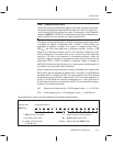
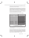
If the reference oscillator is stopped by a programmed disable or by an IDLE
instruction, then, on re-enable or wake-up, the oscillator requires some time
to restart and resume its correct frequency. This time imposes a delay on the
core processor resuming full-speed operation. The time-delay required for the
CRO to start is
greater
than the time-delay required for the RTO to start.
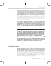
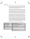
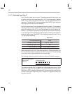
There are a number of ways to wake the C614 from the IDLE-induced sleep
state. The various options are summarized, as a function of the reduced power
mode, in Table 2–5. Naturally, the RESET event (happens after the RESET pin
has gone low-to-high) causes an immediate escape from sleep; whereby, the
program counter assumes the location stored in the RESET interrupt vector.
The RESET escape from sleep is always enabled, regardless of the depth of
sleep or the state of programmable controls.
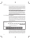
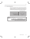
The more functional methods available for waking the device are: 1) the
Internal TIMER interrupt, and 2) the external input-port interrupt. For either of
these options to work, the respective bit in the interrupt mask register (address
0x38) must be set to enable the associated interrupt service. If the appropriate
IMR bit is not set before the IDLE instruction, then the interrupt-trigger event
will not be capable of waking the device from sleep. Note also the state of the
idle state clock control bit and the ARM bit, if you expect to wake-up using
either type of interrupt (internal or external). In most cases, the state of these
bits should coincide Table 2–3.


