


Instruction Syntax and Addressing Modes
4-17
Assembly Language Instructions
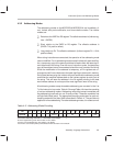
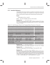
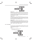
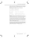
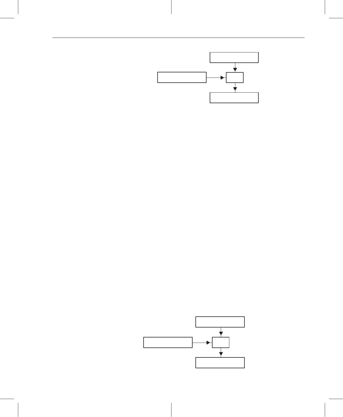
Address
+
Rx
(x = 0 – 7)
Index Register (R5)
Operand
Example 4.3.17 AND A0, *R3+R5
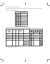
Refer to the initial processor state in Table 4–8 before execution of this instruc-
tion. A0 is accumulator AC2. The contents of the data memory byte location
pointed to by R3+R5 is ANDed with AC2. The result is stored in AC2. The val-
ues in R3 and R5 are unchanged. Final result, AC2 = AC2 AND *0x01F2 =
0x13F0 AND 0x12AC = 0x12A0.
Example 4.3.18 MOV *R2+R5, A2~, ++A
Refer to the initial processor state in Table 4–8 before execution of this instruc-
tion. Preincrement AP2. After preincrement, A2 is AC12 and A2~ is AC28.
Store AC28 in the data memory byte location R2+R5. The values in R2 and
R5 are unchanged. Final result, *0x02A1 = 0x11A2.
Example 4.3.19 ADD A0~, A0, *R4+R5, ––A
Refer to the initial processor state in Table 4–8 before execution of this instruc-
tion. Predecrement AP0. After predecrement, A0 is AC1 and A0~ is AC17. Add
AC1 to the contents of byte location R4+R5 and put the result in AC17. The
values in R4 and R5 are unchanged. Final result, AC17 = AC1 + *(R4+R5) =
0x0007 + *0x0002 = 0x0007 + 0x499A = 0x49A1.
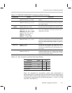
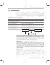
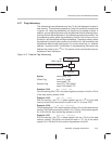
4.3.6.2 Short Relative
Short relative (also called PAGE Relative) addressing selects the Page
register (R6) as a base value and adds a 7-bit positive offset from the operand.
The page register is not modified.
Syntax:
name
[
dest
,] [
src
,] *R6+
offset7
[,
next A
]
name
*R6+
offset7
[,
src
] [,
next A
]
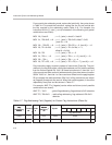
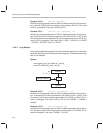
Address
+
R6
PAGE register
7-Bit positive offset
Operand