


MSP50C6xx Software Development Tool
5-3
Code Development Tools
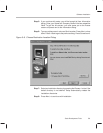
the reset circuit and the reset pin, and connecting the scanport reset signal
directly to the reset pin. See the recommended reset circuit shown in
Figure 1–3.
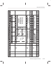
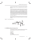
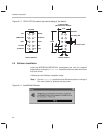
It is also recommended that all production boards be built with the scanport
interface connector footprint connected to the appropriate pins and VPP-level
translator circuit shown in Figure 5–1. This allows the MSP50C6xx Software
Development Tools to facilitate any post production debugging. The 10 pin
connector, transistor, zenor diode, and resistors can be added as needed. The
development tool must be allowed to toggle the reset pin without being loaded
by any low impedance reset circuit. This can be accomplished by inserting a
1-kΩ resistor between the reset circuit and the reset pin, and connecting the
scanport reset signal directly to the reset pin. See the recommended reset
circuit shown in Figure 1–3.
If this is not possible, it would be helpful to provide an easy way to connect the
MSP50C6xx scanport pins to an external level translator circuit and scanport
connector.
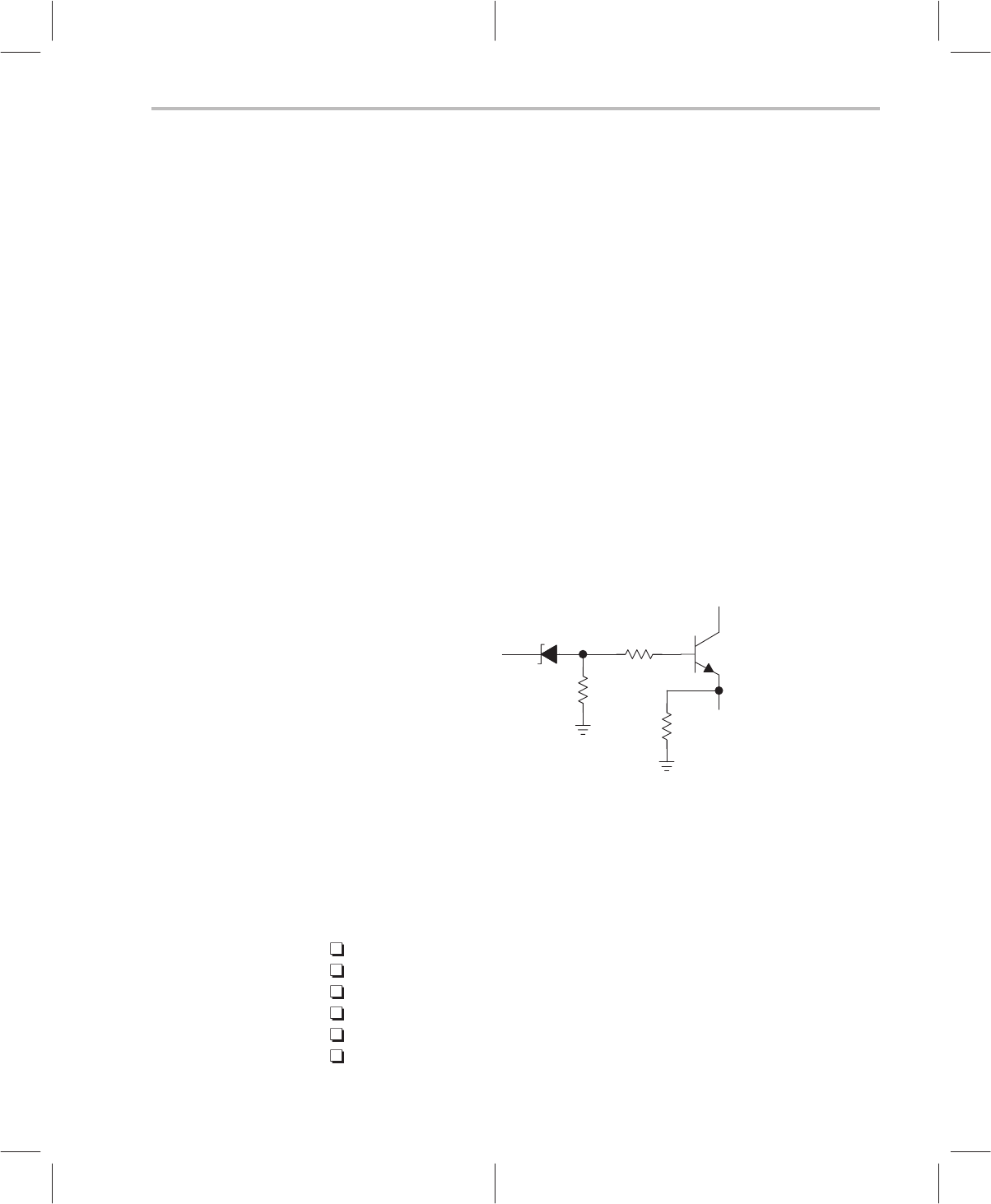
Figure 5–1. Level Translator Circuit
V
PP
5.1 V Zener
100 kΩ
10 kΩ
2N2222
V
DD
TEST
To
MSP50C6xx
Device
To
10-pin
IDC
header
connecting
to
MSP50C6xx
scanport
10 kΩ
5.2 MSP50C6xx Software Development Tool
The development tool software is a Microsoft Windows based integrated
graphical development environment which includes the following:
Assembler
Linker
Make utility
Debugger
C–– compiler
Application programming interface