


Comparator
3-16
The comparator, along with all of its associated functions, is enabled by setting
bit 15 of the interrupt/general control register (IntGenCtrl, address 0x38). The
default value of the register is zero: comparator disabled.
Note: IntGenCtrl Register Bit 15
At the time that bit 15 in the IntGenCtrl is set, PD
4
and PD
5
become the
comparator inputs. At any time during which bit 15 is set, PD
4
and PD
5
MUST
be set to INPUT (I/O Port D Control, address 0x1C, bits 4 and 5 CLEARed).
Failure to do so may result in a bus contention.
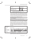
The function of pins PD
4
and PD
5
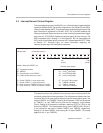
, and the behavior of events COND2, INT6,
INT7, and TIMER1 are very different, depending on whether the comparator
has been enabled or disabled. A summary of the various states appears in the
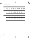
following table:
Comparator ENABLED
SET bit 15 in the IntGenCtrl, address 0x38 . . .
PD
4
functions as comparator negative input
PD
5
functions as comparator positive input
(port D Control, 0x1C, bit 4 MUST be 0)
(port D Control, 0x1C, bit 5 MUST be 0)
COND2 maps to the state of the comparator (PD
5
relative to PD
4
)
INT6 is triggered by a rising edge at PD
5
INT7 is triggered by a falling edge at PD
5
(relative to PD
4
)
TIMER1 may be started by a falling edge at PD
5
TIMER1 will be stopped by a rising edge at PD
5
(assuming TIMER1 Enable is 0)
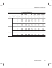
Comparator DISABLED CLEAR bit 15 in the IntGenCtrl, address 0x38 . . .
PD
4
functions as a general I/O pin
PD
5
functions as a general I/O pin
(port D Control 0x1C, bit 4 = 0 or 1)
(port D Control 0x1C, bit 5 = 0 or 1)
COND2 maps to the state of the I/O pin PD
1
(0 or 1 logical)
INT6 is triggered by a rising edge at PD
4
INT7 is triggered by a falling edge at PD
5
(0 to 1 logical)
(1 to 0 logical)
TIMER1 is started/stopped in software by setting/clearing TIMER1 enable (IntGenCtrl)