


Instruction Classification
4-23
Assembly Language Instructions
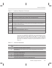
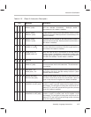
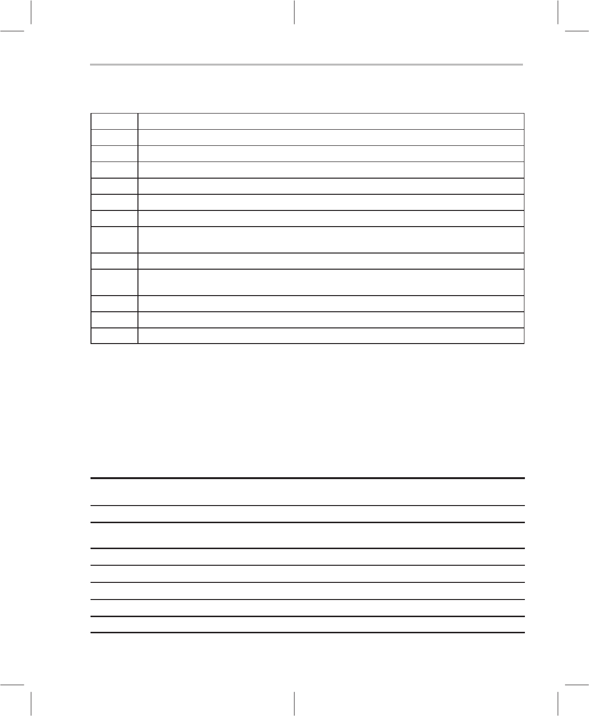
Table 4–11. Symbols and Explanation (Continued)
Symbol Explanation
next A Accumulator control bits as described in Table 4–6.
[
next A
] The preincrement (++A) or predecrement (––A) operation on accumulator pointers A
n
or A
n
~.
Not NOT condition on conditional jumps, conditional calls or test flag instructions.
n
R
Value in the repeat counter loaded by repeat instruction.
n
s
Value in string register STR.
offset[n] n bit offset from a reference register.
pma[n] n bit program memory address. For example, pma8 means 8-bit program memory address. If n
is not specified, defaults to pma16.
port[n] n bit I/O port address.
R R
x
registers are treated as general purpose registers. These bits are not related to any addres-
sing modes.
R
x
Indirect register bits as described in Table 4–3.
s Represents string mode if 1, otherwise normal mode.
x Don’t care
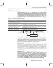
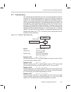
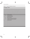
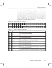
Instructions on the MSP50P614/MSP50C614 are classified based on the op-
erations the instruction group performs (see Table 4–11). Each instruction
group is referred to as a class. There are 9 instruction classes. Classes are
subdivided into subclasses. Classes and opcode definitions are shown in
Table 4–11.
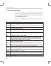
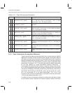
Table 4–11. Instruction Classification
Class Sub-
Class
Description
1 Accumulator and memory reference instructions
A Accumulator and memory references with or without string operations and accumulator
preincrementing
B Accumulator and memory references with or without string operations
2 Accumulator constant reference
A Short constant to accumulator
B Long constant to accumulator
3 Accumulator reference instructions with no addressing modes