


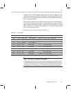
Digital-to-Analog Converter (DAC)
3-10
style
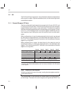
. Their selection is made at bit 3 of the DAC control register (0x34). The
C3x style
is selected by clearing bit 3, and the
C5x style
is selected by setting
bit 3. The default value of the selection is zero which yields the
C3x style
.
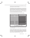
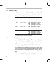
The overflow bits appear in the DAC data register (14 and 13) to the left of the
MSB data bit (12). In the
C3x style
mode, the overflow bits serve as a 2-bit
buffer to handle overflow in the value field (bits 12…3). Any magnitude written
to the value field which is greater than 1023 (up to the limit 4095) lands a 1 in
the overflow. The overflow state (when a 1 appears in either bit 13 or 14) yields
the maximum PDM saturation and delivers the maximum possible current
drive to the loudspeaker. The overflow bits thus help to ensure that the audible
artifacts of
wrap-around
do not occur.
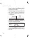
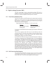
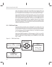
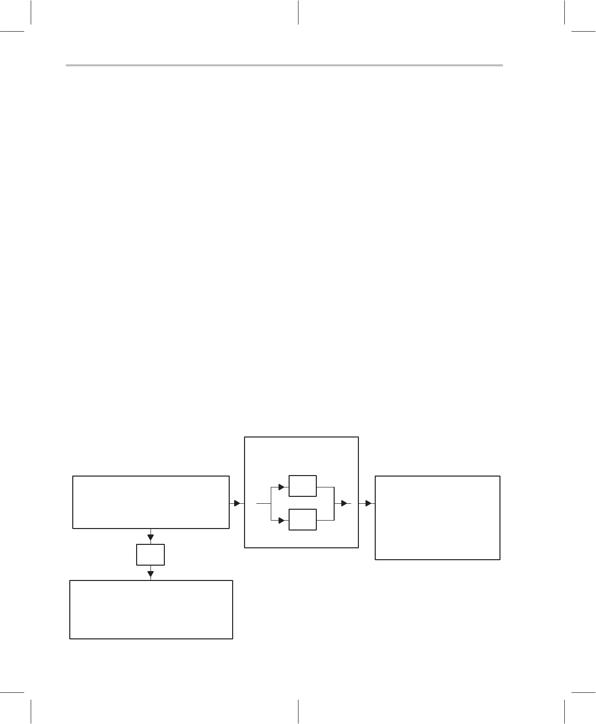
3.2.3 PDM Clock Divider
The pulse-density-modulation rate is determined by the master clock. The
PDM rate may be set equal to the rate of the MC, or it may be set at one-half
the rate of the MC. This option is controlled by the PDM clock divider (PDMCD)
in the interrupt/general control register (IntGenCtrl). The PDMCD is located at
bit 13 in IntGenCtrl (address 0x38).
Clearing the PDMCD bit results in a PDM rate equal to 1/2 MC (i.e., the CPU
Clock rate). Setting the PDMCD bit results in a PDM rate equal to the MC. After
RESET is held low, the default setting for the PDMCD bit is zero (PDM
rate = 1/2 MC).
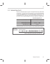
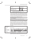
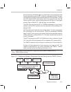
Figure 3–1. PDM Clock Divider
MC
Master Clock : 131.07 kHz ... 33.554 MHz
÷2
CPU Clock
Core-Processor Speed
65.536 kHz ... F
MAX
(8 MHz is max assured : see Chapter 9)
(rate adjusted in ClkSpdCtrl)
PDMCD
PDM Clock Divider
Bit 13 in IntGenCtrl
(frequency)
÷2
x1
0
1
PDM Rate
Pulse-Density-Modulation Rate
Governs DAC Capacity
65.536 kHz ... F
MAX
or
131.07 ... 33.554 MHz