


Individual Instruction Descriptions
4-149
Assembly Language Instructions
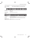
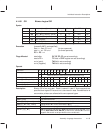
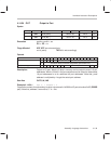
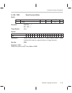
4.14.54 OUT Output to Port
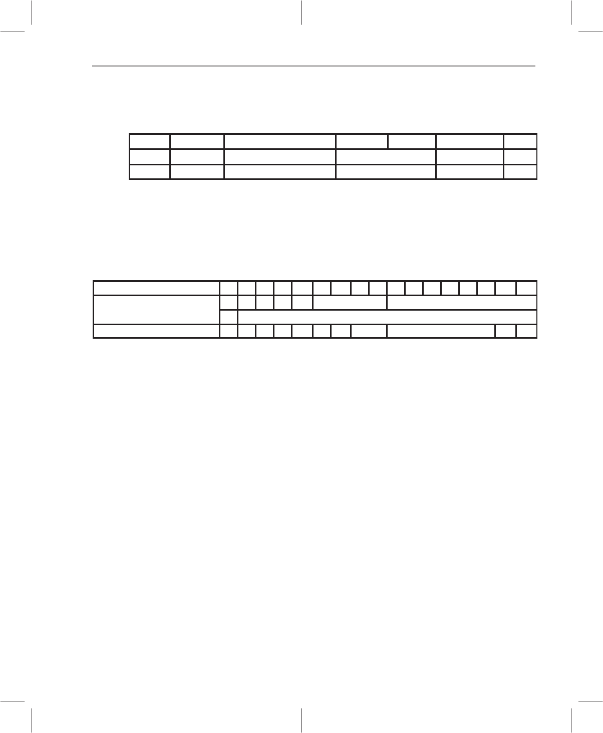
Syntax
[label] name dest, src
Clock,
clk
Word,
w
With RPT,
clk
Class
OUT
port4
, {
adrs
} Table 4–46 n
R
+3 6a
OUT
port6
, A
n
[~] Table 4–46 n
R
+3 6a
Execution
port4
or
port6
⇐
src
PC ⇐ PC +
w
Flags Affected XSF, XZF are set accordingly
src
is {
adrs
}: TAG bit is set accordingly
Opcode
Instructions 16 15 14 13 12 11 10 9 8 7 6 5 4 3 2 1 0
OUT
port4
, {
adrs
}
1 1 0 0 1 port4
adrs
x
dma16
(for direct) or
offset16
(long relative) [see section 4.13]
OUT
port6
, A
n
[~] 1 1 1 0 1 1 0 A
n port6
1 ~A
Description Output to I/O port. Words (16 bits) in memory can be output to one of 16 port
addresses. Words (16 bits) in the accumulators can be output to these same
16 port addresses or to an additional 48 port addresses. Note that,
port4
address is multipled by 4 to get the actual port address.
See Also OUTS, IN, INS
Example 4.14.54.1 OUT 3, * 0x0200 * 2
Outputs the content of word memory location value stored in 0x0200 to I/O port at location 0x0C (PBDIR
port). Note that, address 3 converts to 3 * 4 = 0xc.