Individual Instruction Descriptions
4-103
Assembly Language Instructions
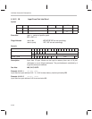
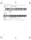
4.14.20 IDLE Halt Processor
Syntax
[label] name
Clock,
clk
Word,
w
With RPT,
clk
Class
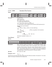
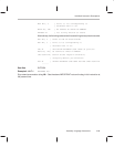
IDLE 1 1 N/R 9d
Execution Stop processor clocks
PC ⇐ PC + 1
Flags Affected None
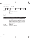
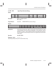
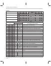
Opcode
Instructions 16 15 14 13 12 11 10 9 8 7 6 5 4 3 2 1 0
IDLE 1 1 1 1 1 1 1 1 0 0 0 1 0 0 0 0 0
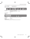
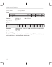
Description Halts execution of processor. An external interrupt wakes the processor. This
instruction is the only instruction to enter one of the three low power modes
defined in section 2.11. Low power modes depend on the state of ClkSpdCtrl
register bit 8 through bit 10 and the ARM bit in IntGenCtrl register.
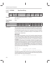
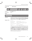
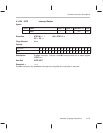
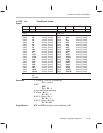
Example 4.14.20.1 MOV A0, 0
OUT 0x34, A0 ; Turn off DAC
MOV A0, 0x0400 ; Turn off clock, idle bit = 1
OUT 0x3d, A0 ; Write in ClkSpdCtrl (write only)
IN A0, 0x38 ; Read IntGenCtrl register value
OR A0, A0, 0x4000 ; Set ARM = 1
OUT 0x38, A0 ; Write to IntGenCtrl
IDLE ; Go to deep sleep mode
To understand this routine, refer to the
Reduced Power Modes
table in section
2.11. The bits to be set up to switch to deep sleep mode are as follows: set bits
10 of ClkSpdCtrl (IO address 0x3d) register to 1 and reset bits 8 and 9 of
ClkSpdCtrl register to 0 (The PLLM bits are reset to zero in this example
which is not a necessary operation). Note that the ClkSpdCtrl register is write
only. Set the ARM bit in the IntGenCtrl (I/O address 0x38) register to 1
(program line 2 and 3 above). The last line executes the IDLE instruction which
switches the processor to deep sleep mode.


