


Reduced Power Modes
2-34
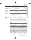
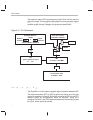
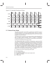
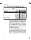
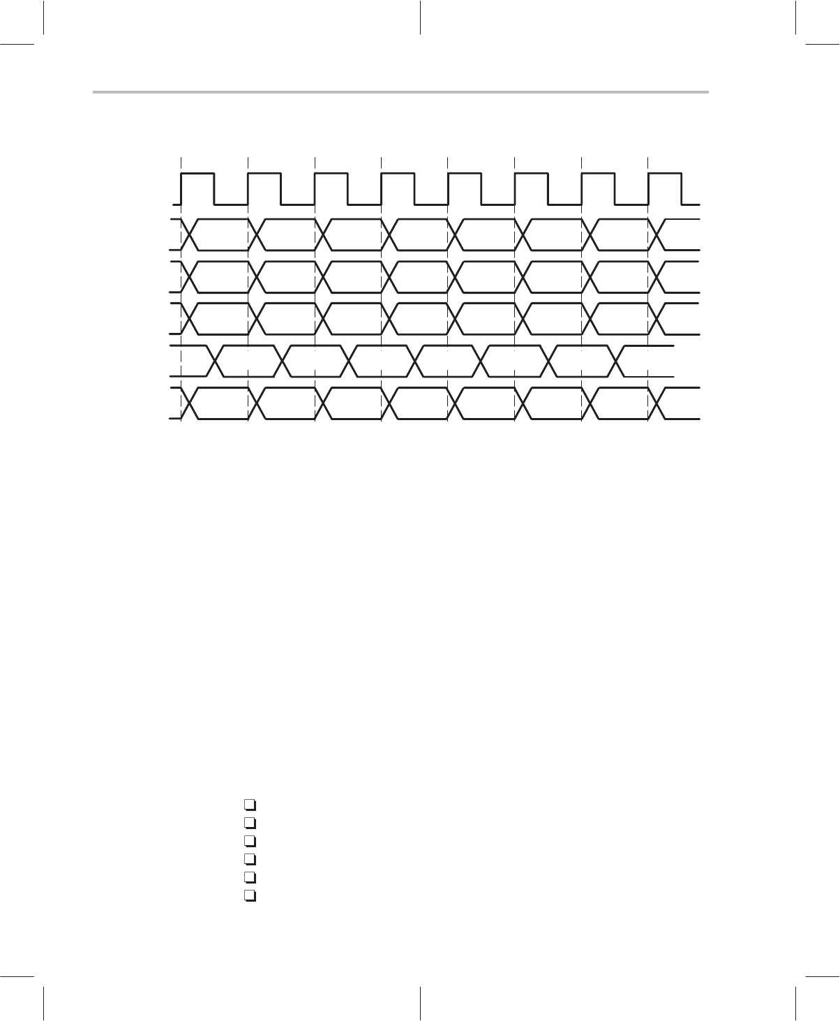
Figure 2–10. Instruction Execution and Timing
N
N+1 N+2
N+3
N+4
N+5 N+6
N+7
FETCH
CLOCK
N–1
N N+1
N+2
N+3
N+4 N+5
DECODE
N–2
N–1 N
N+1
N+2
N+3 N+4
N+5
EXEC
N–1
N N+1
N+2
N+3
N+4 N+5
DATA ADD
N
N+1 N+2
N+3
N+4
N+5 N+6
N+7
PC ADD
2.11 Reduced Power Modes
The power consumption of the C614 is greatest when the DAC circuitry is
called into operation, i.e., when the synthesizer speaks. There are, however,
a number of reduced power modes (sleep states) on the C614 which may be
engaged during quiet intervals.
The performance and flexibility of the reduced power modes make the C614
ideal for battery powered operation. Refer to Chapter 8,
MSP50C614
Electrical Specifications
, for a full description of the electrical characteristics,
including the acceptable power-supply ranges.
The reduced power state on the C614 is achieved by a call to the IDLE
instruction. The idle state is released by some interrupt event. Different modes
(or levels) of reduced-power are brought about by controlling a number of
different core and periphery components on the device. These components
are independently enabled/disabled before engaging the IDLE instruction.
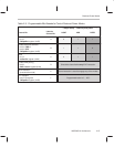
The number of subsystems left running during sleep directly impacts the
overall power consumption during that state. The various subsystems that
determine (or are affected by) the depth of sleep include the:
Processor core, which is driven by the CPU clock
PLL clock circuitry
PLL reference oscillator
C614 periphery, which is driven by the master clock
TIMER1 and TIMER2
PDM pulsing