


Individual Instruction Descriptions
4-102
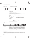
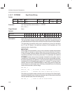
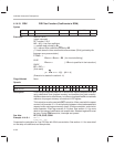
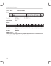
4.14.19 FIRK FIR Filter Function (Coefficients in ROM)
Syntax
[label] name dest, src
Clock,
clk
Word,
w
With RPT,
clk
Class
FIRK A
n
, *R
x
2 1 2(n
R
+2) 9a
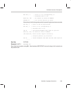
Execution
With RPT
N–2:
(
mask interrupts
)
RPT counter = N–2
MR =
h
[0] = first filter coefficient
x
= sample data pointed by R
x
even
h
[1] = second filter coefficient pointed by DP
y
= result stored in three consecutive accumulators (32 bit) pointed by A
n
[between every accumulation}
IF TAG = 1
R
x
even
= R
x
even
+ R5 {for circular buffering}
ELSE
R
x
even
++ { if R
x
++ is specified in the instruction}
ENDIF
PC ⇐ PC + 1
{final result}
y
k
0..N–1
h
[
k
]·
x
[N
–
1
–k
]
(Execution is detailed in section 4.11)
Flags Affected None
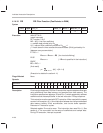
Opcode
Instructions 16 15 14 13 12 11 10 9 8 7 6 5 4 3 2 1 0
FIRK A
n
, *R
x
1 1 1 0 1 0 0 A
n
0 0 0 R
x
1 1
Description Finite impluse response (FIR) filter. Execute finite impulse response filter taps
using coefficients from program memory and samples from data memory.
Address reference for data memory is indirect using specified R
x
and address
reference for program memory is contained in DP register.
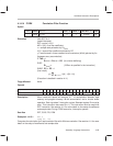
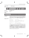
This instruction must be used with RPT instruction. When used with the repeat
counter it will execute 16 × 16 multiplication between indirect addressed data
memory buffer and program memory (coef), 32-bit accumulation, and circular
buffer operation. Each tap executes in 2 cycles. See section 4.11 for more
detail on the setup of coefficents and sample data. Selected register R
x
must
be even. During FIRK execution, interrupts are queued.
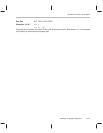
See Also RPT, FIR, COR, CORK
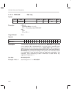
Example 4.14.19.1 RPT 0
FIRK A0, *R0
Computes the calculation for 2 tap FIR filter with 32 bit accumulation. See section 4.11 for more detail
on the setup of coefficients and sample data.