


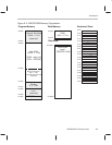


Architecture
B-7
MSP50C604 Preliminary Data
B.3.7 Interrupts
Interrupts for MSP50C604 are the same as MSP50C614 in host mode except
INT5 (port F interrupt) is not available. But in slave mode, INT3 and INT4 are
external interrupts triggered by write sequence and read sequence as ex-
plained before.
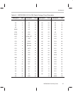
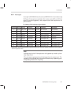
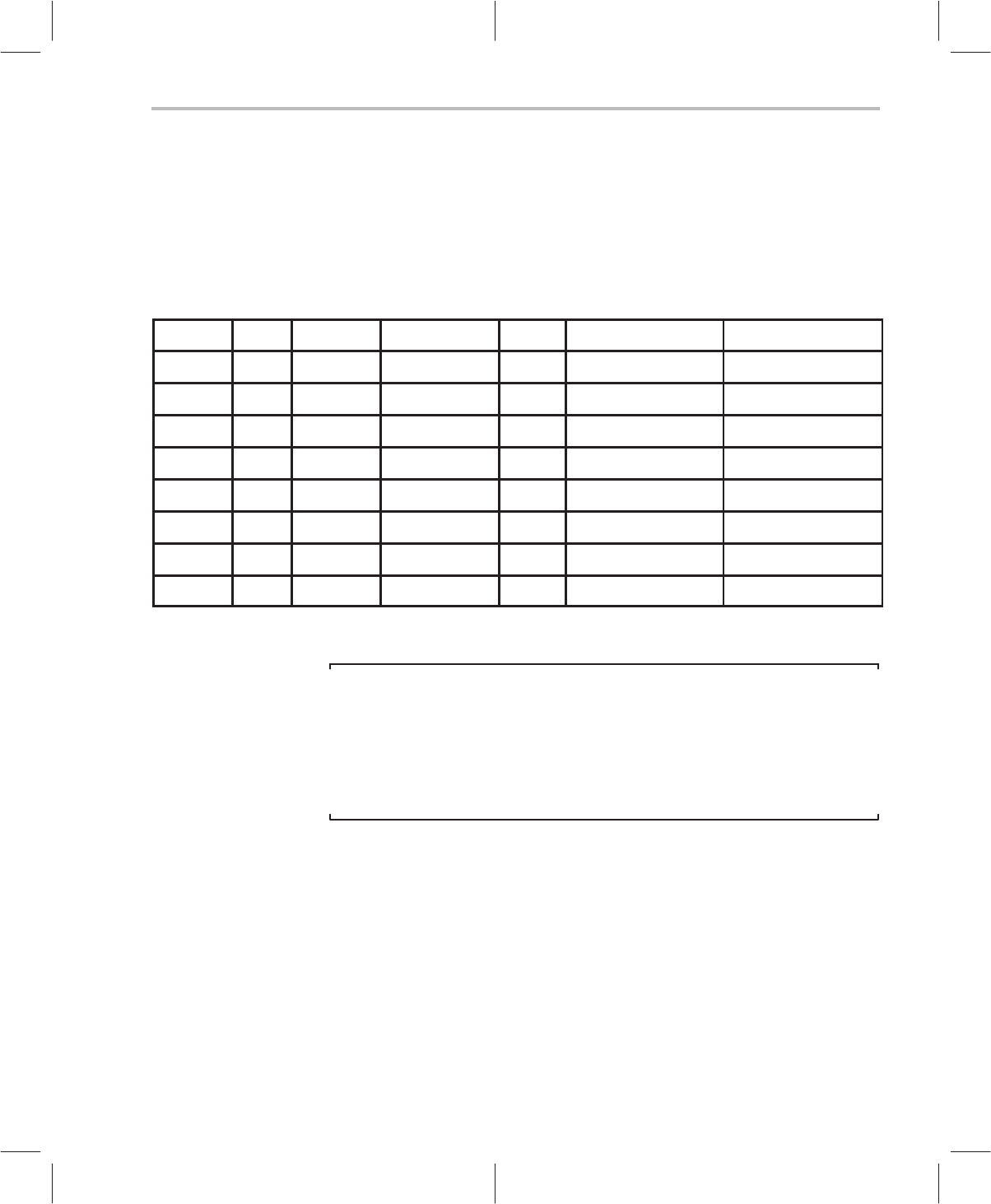
A summary of the interrupts is given below:
Interrupt Vector Source Condition Priority Host Mode Slave Mode
0 7FF0h DAC Timer Timer underflow Highest DAC interrupt Dac interrupt
1 7FF1h TIMER1
Timer underflow
2nd Timer 1 underflow Timer 1 underflow
2 7FF2h TIMER2
Timer underflow
3rd Timer 2 underflow Timer 2 underflow
3 7FF3h Port D2 Rising edge 4th Port D2 goes high Host write
4 7FF4h Port D3
Falling edge
5th Port D3 goes low Host read
5 7FF5h Port F Falling edge 6th Reserved, not used Reserved, not used
6
†
7FF6h Port D4* Rising edge 7th Port D4 goes high
†
Port D4 goes high
†
7
†
7FF7h Port D5* Falling edge Lowest Port D5 goes low
†
Port D5 goes low
†
†
INT6 and INT7 may be associated with the comparator function if the comparator enable bit has been set. See the section en-
titled Comparator for details.
Note:
Interrupts may be lost if interrupts occur during power up or wake up from
deep sleep mode.
The interrupts are generated as a divided signal from the master clock. The
frequency of the several timer interrupts will therefore vary depending upon
the operating master clock frequency.