


I/O
3-2
3.1 I/O
The C614 has 64 input-output pins. Forty of these are software configurable as
either inputs or outputs. Eight are dedicated inputs, and the remaining sixteen
are dedicated outputs.
3.1.1 General-Purpose I/O Ports
The forty configurable input/output pins are organized in 5 ports, A,B,C,D, and
E. Each port is one byte wide. The pins within these ports can be individually
programmed as input or output, in any combination. The selection is made by
clearing or setting the appropriate bit in the associated control register (Control
A, B, C, D, or E). Clearing the bit in the control register renders the pin as a
high-impedance input. Setting the control bit renders the pin as a totem-pole-
output.
When configured as an input, the data presented to the input pin can be read
by referring to the appropriate bit in the associated data register (Data A, B,
C, D, or E). This is done using the IN instruction, with the address of the data
register as an argument.
When configured as an output, the data driven by the output pin can be
controlled by setting or clearing the appropriate bit in the associated data
register. This is done using the OUT instruction, with the address of the data
register as an argument.
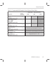
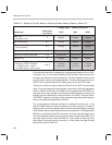
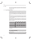
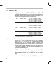
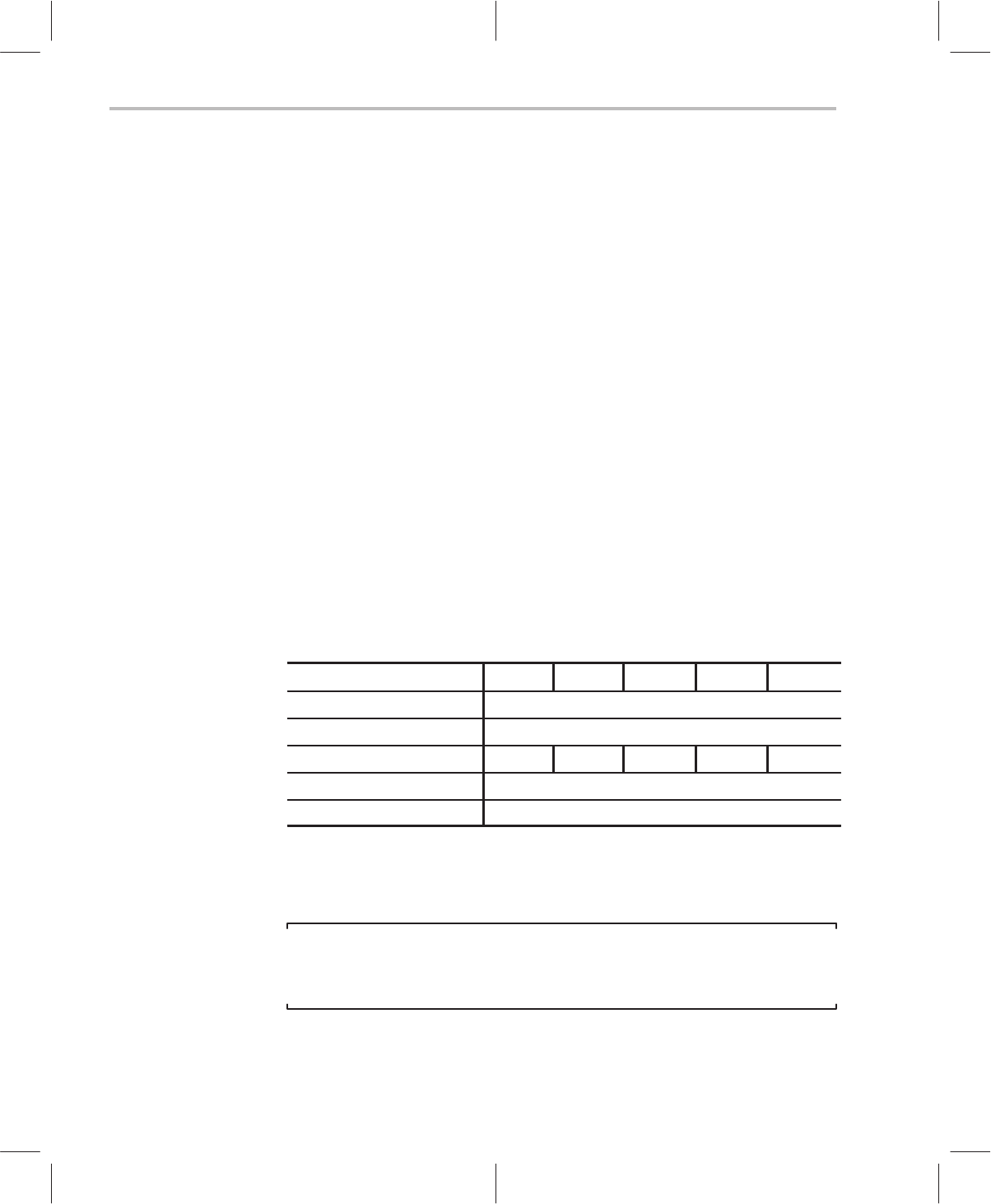
Port A Port B Port C Port D Port E
Control register address
0x04h
†
0x0Ch 0x14h 0x1Ch 0x24h
Possible control values 0 = High-Z INPUT 1 = TOTEM-POLE OUTPUT
Value after RESET low 0 = High-Z INPUT
Data register address 0x00h 0x08h 0x10h 0x18h 0x20h
Possible input data values Low = 0 High = 1 (don’t care on write)
Possible output data values 0 = Low 1 = High
†
Each of these I/O ports is only 8 bits wide. The reason for the 4-byte address spacing is so that
instructions
with limited addressability (such as memory transfers) can still access
these registers.
Note: Reading the Data Register
Whether configured as input or as output, reading the data register reads the
actual state of the pin.
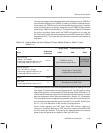
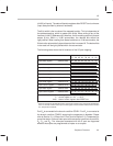
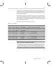
The programmable I/O are initialized to a known state by cycling the RESET
pin low-to-high. The state of the control registers during and after RESET low