


Instruction Syntax and Addressing Modes
4-15
Assembly Language Instructions
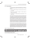
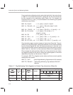
4.3.5 Indirect Addressing
Indirect addressing uses one of 8 registers (R0...R7) to point memory
addresses. The selected register can be post-modified. Modifications include
increments, decrements, or increments by the value in the index register (R5).
For post-modifications, the register increments or decrements itself by 2 for
word operands and by 1 for byte operands. Syntaxes are shown in Table 4–9.
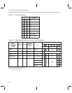
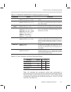
Table 4–9. Indirect Addressing Syntax
Syntax Operation
name [dest,] [src,] ,
*R
x
++R5 [
, next A]
name
*R
x
++R5 [
, src] [, next A]
Premodify accumulator pointer if
next A
is included. Add R
x
with R5.
name [dest,] [src,] ,
*R
x [, next A]
name
*R
x [, src] [, next A]
Premodify accumulator pointer if
next A
is included. Use address
pointed by R
x
, R
x
content unchanged
name [dest,] [src,] ,*
R
x
++
[, next A]
name
*Rx++
[,
src
] [,
next A
]
Premodify accumulator pointer if
next A
is included. Use address
pointed by R
x
, post increment R
x
after use
name [dest,] [src,] ,*
R
x
––
[, next A]
name
*R
x
––
[, src] [, next A]
Premodify accumulator pointer if
next A
is included. Use address
pointed by R
x
, post decrement R
x
after use
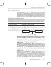
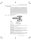
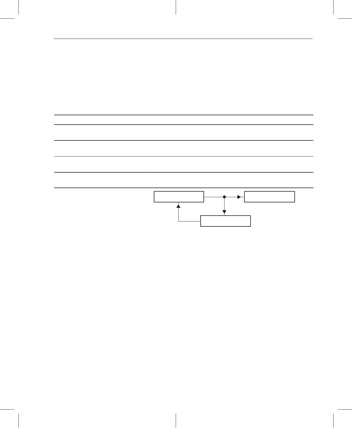
Address
Memory Operand
++ –– ++R5
Rx
(x = 0 – 7)
Note that the R
x
registers treats data memory as a series of bytes. Therefore,
when a word is loaded, R
x
++ increments by 2 (R
x
–– decrements by 2). When
loading a word address into R
x
, the address must be converted into a byte ad-
dress (by multiplying by 2). For example, if we want R
x
to point to the word ad-
dress, 0x100, R
x
should be loaded with 0x100*2=0x200.
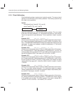
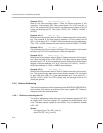
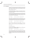
Example 4.3.10 MOV A1~, *R1++R5, ++A
Refer to the initial processor state in Table 4–8 before execution of this
instruction. Preincrement AP1. After preincrement A1 is AC22 and A1~ is AC6.
The contents of the data memory location stored in R1 are loaded into
accumulator AC6. R1 is then incremented by R5. Final result, AP1=22, AC6
= 0xacb, R1 = R1 + R5 = 0x0202. Note that the addressing of the R
x
registers
is byte addressing.
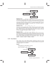
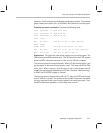
Example 4.3.11 ADD A3~, A3, R6++R5, ––A
Refer to the initial processor state in Table 4–8 before execution of this
instruction. Predecrement AP3. After predecrement, A3 is AC28 and A3~ is
AC12. The contents of the data memory location stored in R6 are added to
AC28. The result is stored in accumulator AC12. R6 is then incremented by
R5. Final result, AP3=28, AC12 = AC28 + *R6 = 0x11A2 + 0x12AC = 0x244E,
R6 = R6+R5 = 0x3E6. Note that the R
x
registers use byte addresses.