Reduced Power Modes
2-39
MSP50C614 Architecture
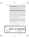
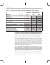
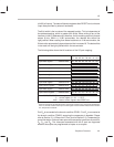
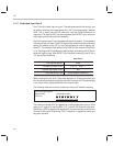
The interrupt-trigger event associated with each of the two internal TIMERs is
the underflow condition of the TIMER. In order for a TIMER underflow to occur
during sleep, the TIMER must be left running before going to sleep. In certain
cases, however, the act of going to sleep can bring a TIMER to stop, thereby
preventing a TIMER-induced wake-up. The bottom row of Table 2–4 illustrates
the various conditions under which the TIMER will continue to run after the
IDLE instruction. Not that the reduced power mode DEEP leaves both TIMERs
stopped after IDLE. This mode cannot, therefore, be used for a timed wake-up
sequence.
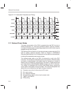
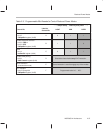
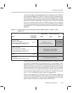
Table 2–5. How to Wake-Up from Reduced Power Modes (Refer to Table 2–3 and
Table 2–4)
→ deeper sleep … relatively less power →
Event
Determined
by Controls
LIGHT MID DEEP
Timer interrupts
TIMER1 and TIMER2
• Assuming respective IMR bit is set
• Assuming ARM bit is set as in
C
A, B, C
If TIMER is running,
then Underflow wakes device.
No wake-up
from TIMER.
External interrupts
Port F and D
2
,
3
,
4
,
5
(if input)
• Assuming respective IMR bit is set
• Assuming ARM bit is set as in
C
C
Rising-Edge, or Falling-Edge,
as appropriate, wakes device.
RESET none
RESET LOW-to-HIGH always wakes device.
DAC Timer
• Assuming PDM bit is clear as in
D
D
No wake-up from DAC Timer.
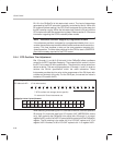
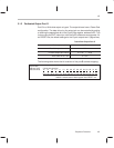
The external interrupt is the other programmable option for waking the C614
from sleep. The associated interrupt-trigger event is, in some cases, a rising-
edge at the input port; in some cases it is a falling-edge. Refer to Section 3.1.5,
Internal and External Interrupts
, for a full description of these events. Consider
also the comparator driven interrupts described in Section 3.3,
Comparator
.
The input ports which are supported by external interrupt include the entire F
Port, and, when programmed as inputs, Ports D
2
, D
3
, D
4
, and D
5
. Refer to Sec-
tion 3.1,
I/O
, for a description of the various I/O configurations.
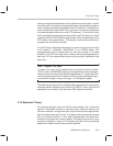
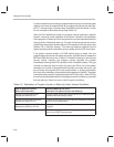
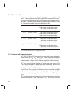
Under normal operation the DAC timer, when IMR enabled, triggers an
interrupt on underflow. Before any IDLE instruction, however, the entire DAC
circuitry should be disabled. This ensures the effectiveness of the reduced
power mode and prevents any wake-up from the DAC timer.


