


I/O
3-7
Peripheral Functions
Registers
). INT1 and INT2 are high-priority, internal interrupts triggered by the
underflow conditions on TIMER1 and TIMER2, respectively. Please refer to
Section 2.8,
Timer Registers
, for a full description of the TIMER controls and
their underflow conditions.
When properly enabled, any of these interrupts may be used to wake the de-
vice up from a reduced-power state. In a deep-sleep state, they can also be
used to wake the device when used in conjunction with the ARM bit. Please
refer to Section 2.11,
Reduced Power Modes
, for information regarding the
C614’s reduced power modes.
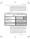
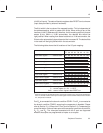
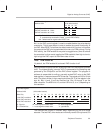
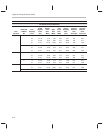
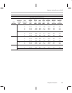
A summary of the interrupts is given in Table 3–1.
Table 3–1. Interrupts
Interrupt Vector Source Trigger Event Priority Comment
INT0 0x7FF0 DAC Timer Timer underflow Highest Used to synch. speech data
INT1 0x7FF1 TIMER1 Timer underflow 2
nd
INT2 0x7FF2 TIMER2 Timer underflow 3
rd
INT3 0x7FF3 PD
2
Rising edge 4
th
Port D
2
goes high
INT4 0x7FF4 PD
3
Falling edge 5
th
Port D
3
goes low
INT5 0x7FF5 All port F Any falling edge 6
th
Any F port pin goes from all-high to low
INT6
†
0x7FF6 PD
4
Rising edge 7
th
Port D
4
goes high
INT7
†
0x7FF7 PD
5
Falling edge Lowest Port D
5
goes low
†
INT6 and INT7 may be associated instead with the Comparator function, if the Comparator Enable bit has been set.
Note: Interrupts in Reduced Power Mode
An interrupt may be lost if its event occurs during power-up or wake-up from
a reduced power mode. Also, note that interrupts are generated as a divided
signal from the master clock. The frequency of the various timer interrupts
will therefore vary, depending upon the operating master clock frequency.