


ICS-2100 Ion Chromatography System
42 Doc. 065291-01 3/09
the EPM to achieve the desired 3.50 mM K
2
CO
3
/1.00 mM KHCO
3
mixture.
2.4.5 Auxiliary Power Supply (Optional)
The EGC-2 power supply can be configured as an auxiliary power supply
for the operation of an electrolytic device such as a water purifier. The
power supply operates in constant current mode and can be configured
from 0 to 200 mA, with a maximum voltage of 35 V.
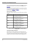
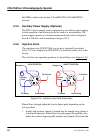
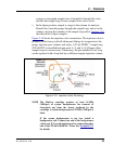
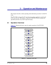
2.4.6 Injection Valve
The injection valve (P/N 057968) is a six-port, electrically-activated
valve. A 25-μL sample loop (P/N 042857) is installed on the valve at the
factory.
The valve has two operating positions: Load and Inject (see Figure 2-18
).
Eluent flows through either the Load or Inject path, depending on the
valve position.
• In the Load position, sample is loaded into the sample loop, where it
is held until injection. Eluent flows from the pump, through the valve,
and to the column, bypassing the sample loop. Sample flows from the
Figure 2-18. Injection Valve Flow Schematics
To Waste
Sample In
To Column
From Pum
p
Sample
Loop
LOAD POSITION
To Waste
Sample In
From Pum
p
Sample
Loop
INJECT POSITION
To Colum
n