


C • TTL and Relay Control
Doc. 065291-01 3/09 247
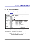
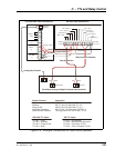
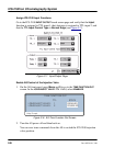
Figure C-6. Example Connections for Stand-Alone Operation
ICS-2100 TTL Inputs
TTL IN 1 = Inject
TTL IN 2 = Autozero
TTL IN 3 = Pump On/Off
TTL IN 4 = Mark
AS TTL Inputs
TTL IN 1 = (unassigned)
TTL IN 2 = Start/Continue Schedule
TTL IN 3 = Tray/Temp. On/Off
TTL IN 4 = Therm. Compart. On/Off
System Function
Inject
Autozero
Start/Continue Schedule
Pump On/Off
Start Data Acquisition
AS TTL Out 1 to ICS-2100 TTL In 1
to AS TTL In 2
AS TTL Out 2 to ICS-2100 TTL In 2
AS RLY Out 2 to ICS-2100 TTL In 3
AS RLY Out 1 to Third-party DAC RLY In
Third-party ADC RLY OUT
Connection
Analog Data Transfer
AS Rear Panel Connections
ICS-2100 Rear Panel Connections
red: pos. 7,8,9
1
234
5
6789101112
1
2
(+)
TTL OUT
1
2
TTL GND
(-)
1
2
3
4
TTL IN
(+)
1
2
RELAY
OUT
TTL 2 OUT (+)
TTL 1 OUT (+)
RLY 2 OUT
RLY 1 OUT
TTL 1 IN (+)
TTL 2 IN (+)
TTL 3 IN (+)
TTL 4 IN (+)
TTL
IN/OUT (-)
Third-Party Analog-to-Digital Converter and Controller
RELAY OUT
red pos.
1,3,5,6
red black red black
Start/Continue Schedule
Inject
1
2
3
4
5
6
7
8
9
10
11
12
black pos.
4,11,12,12
Autozero
ANALOG
OUTPUT
+
-
ANALOG IN
Pump On/Off
black:
pos. 11,12,12
Start Acquisition
RELAY IN