


ICS-2100 Ion Chromatography System
240 Doc. 065291-01 3/09
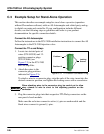
The outputs can be used to control functions in external devices such as an
autosampler or another Dionex module. When connected to a controlling device,
the inputs can be programmed to perform the following ICS-2100 functions:
• Switch the injection valve position (load/inject)
• Perform an autozero command (set the conductivity to zero)
• Turn the pump on and off (also turns the suppressor on and off)
• Automatically turn on the optional auxiliary power supply simultaneously
with the pump flow
• Send a chart mark signal to the analog output. The mark is 10% of the full-
scale voltage, and the duration is 0.5 seconds. A mark can be used, for
example, to indicate the injection.
Relay outputs 1 and 2 can be programmed to switch any low-voltage control.
Switched current must be less than 200 mA and 42 V peak.
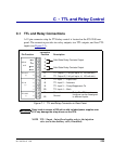
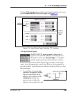
Connecting a TTL or Relay
1. Locate the twisted pair of
wires (P/N 043598) and the
12-position connector plug
(P/N 923687) (see
Figure C-2
) in the ICS-2100
Ship Kit (P/N 064375).
2. Follow these basic steps to
connect the TTL or relays.
a. For each relay or TTL to
be used, connect an
active wire (red) and a ground wire (black) to the 12-position connector
plug at the appropriate pin locations. Refer to Figure C-1
or the label on
the ICS-2100 rear panel for the connector pin assignments.
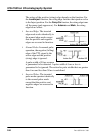
To attach a wire to the plug, strip the end of the wire, insert it into the
plug, and use a screwdriver to tighten the locking screw. If necessary,
multiple ground wires can be attached to a single TTL input/output
ground pin.
When attaching wires to the connector plug, be careful not to allow
stray strands of wire to short to the adjoining position on the
connector.
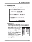
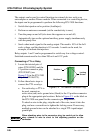
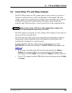
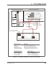
Figure C-2. 12-Position Connector Plug
Position 1
Position 12
Lockin
g
Screws