


B • Touch Screen Operation
Doc. 065291-01 3/09 233
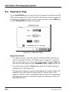
B.10.3 Setting Analog Out Options
The analog output connector on the ICS-2100 rear panel outputs an
analog voltage signal proportional to the conductivity measured by the
cell. The output is filtered using the selected data rise time (see
Section B.10.1
). The analog output can be connected to an analog-to-
digital converter device, such as an integrator or a chart recorder.
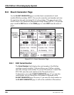
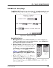
The
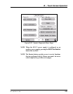
Analog Out options on the DETECTOR page (see Figure B-19) let
you configure the output for your application.
• Output: Select Normal to output a signal corresponding to the offset
conductivity reading from the detector (see “Conductivity Readings”
on page 215) and the selected Analog Out parameters. Use the other
two settings to calibrate an analog-to-digital converter device. Select
Zero to set the output signal to zero volts. Select Full Scale to set the
output signal to the full-scale voltage (1000 mV).
• % Offset: To adjust the zero position of the analog output when it is
plotted, enter a percentage in the
% Offset field. The value entered is
a percentage of the full-scale analog output. An offset allows a
recording device to plot the signal if it becomes negative. The offset
percentage does not affect the magnitude of the output signal.
• Polarity: Select the polarity of the analog output signal: positive (the
default settings) or negative. In applications in which the analyte
output is lower than the background conductance, the polarity must
be negative to have peaks instead of dips on the chromatogram.
• Range: Select the range in microSiemens (μS) of a full-scale detector
response. For the ICS-2100, the full-scale voltage is 1000 mV. For
example, if the range is 100
μS, then 1 μS is equal to 10 mV from the
analog output. The range to use depends on the conductivity readings
expected for the application.