


2 • Features
Doc. 065291-01 3/09 27
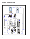
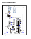
Flow Description for Carbonate/Bicarbonate Eluent Generation
Refer to Figure 2-11 for the flow path number locations.
• Deionized water from the reservoirn flows first through the pump degas
assembly and then through the eluent valve
o to the pumpp. The water is
then pushed through the pressure transducer
q, which measures the system
pressure. From there, the water flows through a pulse damper
r, which
smooths minor pressure variations from the pump to minimize baseline noise.
• Water then flows into the EluGen cartridge (EGC)s, which generates the
programmed concentration of carbonate eluent. Eluent exits the cartridge and
flows through the EPM
t, which adjusts the eluent concentration to produce
the carbonate/bicarbonate mixture. The mixture flows through the EGC degas
tubing assembly
u to the EGC CO
3
Mixerv (to ensure a homogenous
carbonate/bicarbonate mixture), and then on to the injection valve
w.
• After sample is loaded into the sample loop and the injection valve is toggled
to the Inject position, eluent passes through the sample loop.
• The eluent/sample mixture is pumped through the heat exchanger , which
heats the mixture to the column heater temperature. The mixture then goes to
the guard and separator columns and through the suppressor .
• From the suppressor, the mixture flows through the cell , where the analytes
are detected. A digital signal is sent to Chromeleon software. Analog output
can be collected simultaneously.
• The mixture flows out of the cell and is recycled back into the suppressor ,
where it is the water source for the regenerant chamber.
• Regenerant waste from the suppressor is directed back to the EPM , and
then to the EGC degas tubing , where any released hydrogen or oxygen gas
is removed before it is sent to the gas separator assembly and then to waste .
12
13
14
15
16
17
18
19