


Doc. 065291-01 3/09 239
C • TTL and Relay Control
C.1 TTL and Relay Connections
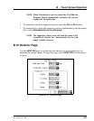
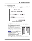
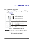
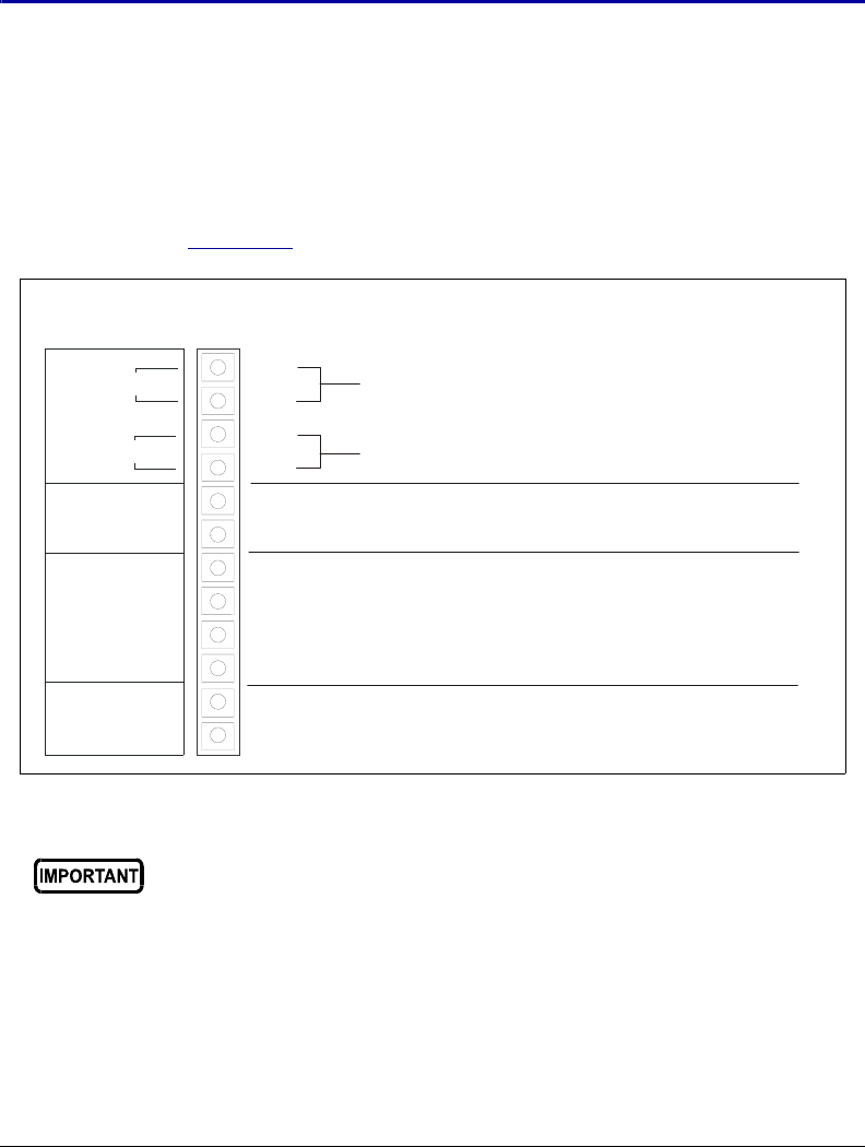
A 12-pin connector strip for TTL/relay control is located on the ICS-2100 rear
panel. The connector provides two relay outputs, two TTL outputs, and four TTL
inputs (see Figure C-1
).
NOTE TTL 1 Input - Inject/Load applies only to the injection
valve (not to the auxiliary valve, if installed).
Figure C-1. TTL and Relay Connector on Rear Panel
Relay loads in excess of 200 mA or with included power supplies over
60 V may damage the relay drivers on the CPU.
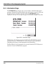
1
2
OUT
RELAY
(+)
TTL OUT
1
2
TTL GND
(-)
1
2
3
4
TTL IN
(+)
1
2
1
2
Description
Solid State Relay Contacts Output
Pin Function
3
4
Solid State Relay Contacts Output
TTL Output 1 (1 k pull up to +5, 100 mA sink)
Ω
5
TTL Output 2 (1 k pull up to +5, 100 mA sink)
Ω
6
7
8
9
10
11
12
Ground
Ground
TTL Input 2
⎯
Autozero
TTL Input 3 Pump/Suppressor On
⎯
TTL Input 4 Mark
⎯
Note:
The TTL input
functions can be reassigned
to different inputs.
C
onnector
Position
TTL Input 1
⎯
Inject/Load