4.7 Configure pressure compensation
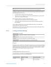
Pressure compensation adjusts process measurement to compensate for the pressure
effect on the sensor. The pressure effect is the change in the sensor’s sensitivity to flow
and density caused by the difference between the calibration pressure and the process
pressure.
Tip
Not all sensors or applications require pressure compensation. The pressure effect for a specific
sensor model can be found in the product data sheet located at www.micromotion.com. If you are
uncertain about implementing pressure compensation, contact Micro Motion customer service.
4.7.1 Configure pressure compensation using ProLink II
Prerequisites
You will need the flow factor, density factor, and calibration pressure values for your
sensor.
• For the flow factor and density factor, see the product data sheet for your sensor.
• For the calibration pressure, see the calibration sheet for your sensor. If the data is
unavailable, use 20 PSI.
Procedure
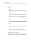
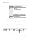
1. Choose View > Preferences and ensure that Enable External Pressure Compensation is
checked.
2. Choose ProLink > Configuration > Pressure.
3. Enter Flow Factor for your sensor.
The flow factor is the percent change in the flow rate per PSI. When entering the
value, reverse the sign.
Example:
If the flow factor is 0.000004 % per PSI, enter −0.000004 % per PSI.
4. Enter Density Factor for your sensor.
The density factor is the change in fluid density, in g/cm
3
/PSI. When entering the
value, reverse the sign.
Example:
If the density factor is 0.000006 g/cm
3
/PSI, enter −0.000006 g/cm3/PSI.
5. Enter Cal Pressure for your sensor.
The calibration pressure is the pressure at which your sensor was calibrated, and
defines the pressure at which there is no pressure effect. If the data is unavailable,
enter 20 PSI.
Configure process measurement
52 Micro Motion
®
Model 1700 Transmitters with Analog Outputs


