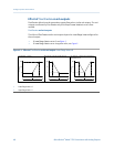
• Under conditions of forward flow, if (the absolute value of) the flow rate equals or
exceeds 100 g/sec, the mA output is proportional to the flow rate up to 20.5 mA,
and will be level at 20.5 mA at higher flow rates.
• Under conditions of reverse flow, for flow rates between 0 and −100 g/sec, the mA
output varies between 4 mA and 12 mA in inverse proportion to the absolute value
of the flow rate.
• Under conditions of reverse flow, if the absolute value of the flow rate equals or
exceeds 100 g/sec, the mA output is inversely proportional to the flow rate down to
3.8 mA, and will be level at 3.8 mA at higher absolute values.
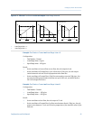
Example: Flow Direction = Reverse
Configuration:
• Flow Direction = Reverse
• Lower Range Value = 0 g/sec
• Upper Range Value = 100 g/sec
Result:
• Under conditions of forward flow or zero flow, the mA output is 4 mA.
• Under conditions of reverse flow, for flow rates between 0 and +100 g/sec, the mA
output level varies between 4 mA and 20 mA in proportion to the absolute value of
the flow rate.
• Under conditions of reverse flow, if the absolute value of the flow rate equals or
exceeds 100 g/sec, the mA output will be proportional to the absolute value of the
flow rate up to 20.5 mA, and will be level at 20.5 mA at higher absolute values.
Effect of Flow Direction on frequency outputs
Flow Direction affects how the transmitter reports flow values via the frequency outputs. The
frequency outputs are affected by Flow Direction only if Frequency Output Process Variable is set
to a flow variable.
Effect of the Flow Direction parameter and actual flow direction on frequency
outputs
Table 4-6:
Flow Direction setting
Actual flow direction
Forward Zero flow Reverse
Forward Hz > 0 0 Hz 0 Hz
Reverse 0 Hz 0 Hz Hz > 0
Bidirectional Hz > 0 0 Hz Hz > 0
Absolute Value Hz > 0 0 Hz Hz > 0
Negate Forward 0 Hz 0 Hz Hz > 0
Negate Bidirectional Hz > 0 0 Hz Hz > 0
Configure process measurement
42 Micro Motion
®
Model 1700 Transmitters with Analog Outputs


