


Example: Concatenating FCF and FT
FCF = x.xxxx
FT = y.yy
Flow calibration parameter: x.xxxxy.yy
Example: Splitting the concatenated Flowcal or FCF value
Flow calibration parameter: x.xxxxy.yy
FCF = x.xxxx
FT = y.yy
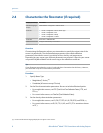
2.4.3 Density calibration parameters (D1, D2, K1, K2, FD, DT,
TC)
Density calibration parameters are typically on the sensor tag and the calibration
certificate.
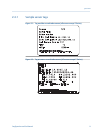
If your sensor tag does not show a D1 or D2 value:
• For D1, enter the Dens A or D1 value from the calibration certificate. This value is the
line-condition density of the low-density calibration fluid. Micro Motion uses air. If
you cannot find a Dens A or D1 value, enter 0.001 g/cm
3
.
• For D2, enter the Dens B or D2 value from the calibration certificate. This value is the
line-condition density of the high-density calibration fluid. Micro Motion uses water.
If you cannot find a Dens B or D2 value, enter 0.998 g/cm
3
.
If your sensor tag does not show a K1 or K2 value:
• For K1, enter the first 5 digits of the density calibration factor. In the sample tag, this
value is shown as 12500.
• For K2, enter the second 5 digits of the density calibration factor. In the sample tag,
this value is shown as 14286.
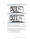
If your sensor does not show an FD value, contact Micro Motion customer service.
If your sensor tag does not show a DT or TC value, enter the last 3 digits of the density
calibration factor. In the sample tag, this value is shown as 4.44.
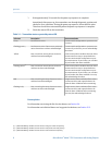
2.5 Verify mass flow measurement
Check to see that the mass flow rate reported by the transmitter is accurate. You can use
any available method.
• Read the value for Mass Flow Rate on the transmitter display.
• Connect to the transmitter with ProLink II and read the value for Mass Flow Rate in the
Process Variables window (ProLink > Process Variables).
• Connect to the transmitter with ProLink III and read the value for Mass Flow Rate in
the Process Variables panel.
Quick start
Configuration and Use Manual 11