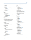
measurement units
configuring 34
options 34
standard density 33
volume flow type 33
ground 329
grounding
troubleshooting 193
GSV, See gas standard volume flow measurement
H
HART
address 102, 106, 204
burst mode 104, 204
device description (DD) 302
HART/Bell 202
configuring 102
Field Communicator connections 303
HART/RS-485
configuring 106
loop 203
Loop Current Mode 102, 204
variables
configuring 105
interaction with transmitter outputs 106
options 105
hysteresis 95
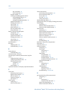
I
I/O terminals 330
informational parameters 76
installation types
4-wire remote 325
9-wire remote 325
high-temperature flexible conduit 325
integral 325
remote core processor with remote transmitter 325
inventories
resetting 132
starting and stopping 129
L
language
for display 58
Last Measured Value Timeout, See Fault Timeout
LD Optimization 161, 163, 164
LED, See status LED
local display, See display
Local Operator Interface (LOI), See display
Loop Current Mode 102, 204
loop testing
using ProLink II 197
using ProLink III 198
using the display 194, 195
using the Field Communicator 200
Lower Range Value (LRV) 82
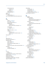
M
mA outputs
Added Damping
configuring 85
interaction with density damping 48
interaction with flow damping 25
AO cutoff
configuring 84
interaction with volume flow cutoff 31
configuring 81
Fault Action
configuring 87
options 87
loop testing
using ProLink II 197
using ProLink III 198
using the display 194, 195
using the Field Communicator 200
Lower Range Value and Upper Range Value
configuring 82
default values 83
process variable
configuring 81
options 82
scaling 82
trimming
using ProLink II 201
using ProLink III 202
using the Field Communicator 202
troubleshooting 190, 204
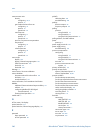
mass flow measurement
configuring 21
cutoff
configuring 25
effect on volume measurement 26
interaction with AO cutoff 26
flow damping 24
measurement units
configuring 21
options 22
meter factor 159
troubleshooting 186
Maximum Pulse Width 91
Index
Configuration and Use Manual 339


