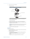
5. At the core processor, disconnect the 4-wire cable between the core processor and
the transmitter.
6. Measure the resistance between core processor terminal pairs 3–4, 2–3, and 2–4.
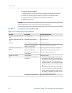
Terminal pair Function Expected resistance
3–4 RS-485/A and RS-485/B 40 kΩ to 50 kΩ
2–3 VDC– and RS-485/A 20 kΩ to 25 kΩ
2–4 VDC– and RS-485/B 20 kΩ to 25 kΩ
7. If any resistance measurements are lower than specified, the core processor may
not be able to communicate with a transmitter or a remote host. The meter may
need factory service.
Postrequisites
To return to normal operation:
• For a 4-wire remote installation or a remote core processor with remote transmitter
installation:
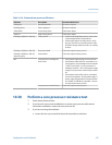
1. Reconnect the 4-wire cable between the core processor and the transmitter.
2. Replace the core processor lid.
3. Restore power to the transmitter.
• For an integral installation:
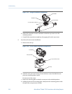
1. Reconnect the 4-wire cable between the core processor and the transmitter.
2. Without pinching or stretching the wires, lower the transmitter onto the base,
inserting the cap screws into the slots.
3. Rotate the transmitter clockwise so that the cap screws are in the locked
position.
4. Tighten the cap screws, torquing to 20 to 30 in-lbs (2.3 to 3.4 N-m).
5. Restore power to the transmitter.
• For a 9-wire remote installation:
1. Reconnect the 4-wire cable between the core processor and the transmitter.
2. Without pinching or stressing the wires, slide the mounting plate into place.
3. Rotate the mounting plate so that the screws are in the locked position.
4. Tighten the screws, torquing to 6 to 8 in-lbs (0.7 to 0.9 N-m).
5. Replace the end-cap.
6. Restore power to the transmitter.
Important
When reassembling the meter components, be sure to grease all O-rings.
Troubleshooting
Configuration and Use Manual 217


